Difference between revisions of "Assignment 2 Part 3: Build an epi-illuminator for your microscope"
Juliesutton (Talk | contribs) (→Fluorescence imaging) |
MAXINE JONAS (Talk | contribs) (→Flat field correction) |
||
| (23 intermediate revisions by 3 users not shown) | |||
| Line 7: | Line 7: | ||
[[Image:20.309 130911 YourMicroscope.png|thumb|260px|right|Fluorescence microscope block diagram.]] | [[Image:20.309 130911 YourMicroscope.png|thumb|260px|right|Fluorescence microscope block diagram.]] | ||
| − | In this part of the | + | It's time to start building! In this part of the assignment, you're going to modify your microscope to add the fluorescence capabilities we talked about in Part 2. You'll then test out these new capabilities by recording images of fluorescent microspheres. Finally, you'll process those images using a flat-field correction to adjust for non-uniform illumination. Once you've completed this assignment, you should be ready for next week when you'll make beautiful images of stained actin filaments inside of mammalian cells! |
| + | |||
| + | <br/> | ||
| + | <br/> | ||
<br/> | <br/> | ||
| − | == | + | ==High power light source safety== |
{{Template:Safety Warning|message= | {{Template:Safety Warning|message= | ||
| − | In this part of the lab, you will use a | + | In this part of the lab, you will use a ~3W green LED with focusing optics. While LEDs are more diffuse than lasers, they still have the potential to cause harm to your eyes. You must attend the safety lecture before you work with high power LEDs in lab. See an instructor if you missed the lecture. Do not begin working with the green LED until you thoroughly understand how to use it safely. |
| − | Stop working and ask an instructor immediately if you have any questions about working with lasers safely. | + | Stop working and ask an instructor immediately if you have any questions about working with lasers or high-power LEDs safely. |
| − | When you work with | + | When you work with high power light sources, keep these best practices in mind: |
| − | * Remove reflective clothing items and jewelry | + | * Remove reflective clothing items and jewelry. |
| − | * Use the lowest possible power during alignment or adjustment. | + | * Use the lowest possible power during alignment or adjustment - for LEDs, that means work at a low current level, for lasers, that means using a neutral density filter to reduce the laser power. |
| − | * Do not use reflective tools when the | + | * Do not use reflective tools when the light source is on. |
* Know the beam path at all times. | * Know the beam path at all times. | ||
** Use a stop to prevent uncontained beams. | ** Use a stop to prevent uncontained beams. | ||
** Secure the stop so it will not move accidentally. | ** Secure the stop so it will not move accidentally. | ||
** Keep your eyes out of the plane of the beam, which his normally a plane just above the optical table. | ** Keep your eyes out of the plane of the beam, which his normally a plane just above the optical table. | ||
| − | * Disable | + | * Disable light sources when they are not in use. |
* Use the correct safety goggles. | * Use the correct safety goggles. | ||
| − | ** Always check the marking on the goggles to ensure they are appropriate for the | + | ** Always check the marking on the goggles to ensure they are appropriate for the light sources you are working with. |
| − | ** | + | ** Safety goggles are a last line of defense, not an excuse for unsafe practices. |
| − | * Do not operate a | + | * Do not operate a high-power light source unless the flashing laser warning sign is on. |
Some specific ways to work safely with the 20.309 fluorescence microscope: | Some specific ways to work safely with the 20.309 fluorescence microscope: | ||
| − | * Use an OD = 2 neutral density (ND) filter to attenuate | + | * Use an OD = 2 neutral density (ND) filter to attenuate a laser near the source. |
** "OD" is an abbreviation for "optical density," which is log<sub>10</sub> of the power transmitted by the filter divided by the incident power. | ** "OD" is an abbreviation for "optical density," which is log<sub>10</sub> of the power transmitted by the filter divided by the incident power. | ||
** "ND" means that the OD is equal for all wavelengths. | ** "ND" means that the OD is equal for all wavelengths. | ||
| − | ** The ND filter attenuates the power of the | + | ** The ND filter attenuates the power of the light by a factor of 10<sup>2</sup>. |
** Mount the ND filter securely so there is no chance that it will get knocked out of place accidentally. | ** Mount the ND filter securely so there is no chance that it will get knocked out of place accidentally. | ||
| − | * The inverted microscope design directs | + | * The inverted microscope design directs illumination light upward, toward the ceiling. Cover the objective and sample with a box and avoid looking directly at the bare objective when the light source is at full power. Do not lean over the objective mount. Use a stop to prevent the beam from propagating above your microscope. |
| − | * Confine beams inside lens tubes. | + | * Confine beams inside lens tubes or plastic pipes. |
| − | * Disable the | + | * Disable the light source when it is unattended or stored by removing a battery, disconnecting the power source, or removing the key. |
* Safety goggles for the laser in this lab should have an OD of at least 2 at 532 nm. | * Safety goggles for the laser in this lab should have an OD of at least 2 at 532 nm. | ||
** There are (at least) two different kinds of safety goggles in the lab that are appropriate for this lab. One has an OD of 2 at 532 nm and the other has an OD of 5. You can see the beam with the OD = 2 goggles, but the power is reduced to a safe level. This makes the OD 2 laser goggles very useful for making adjustments that must be done at full power. | ** There are (at least) two different kinds of safety goggles in the lab that are appropriate for this lab. One has an OD of 2 at 532 nm and the other has an OD of 5. You can see the beam with the OD = 2 goggles, but the power is reduced to a safe level. This makes the OD 2 laser goggles very useful for making adjustments that must be done at full power. | ||
}} | }} | ||
| − | ==Add | + | ==Add fluorescence capabilities to your microscope== |
| − | [[Image: | + | |
| − | # Go over your design with one of the instructors before you start building. | + | ===Add illuminator and dichroic mirror=== |
| − | # | + | [[Image:LedEpifluorescenceMicroscope.png|thumb|center|400px|Layout of fluorescence microscope.]] |
| − | + | Use your design from Part 2 and the example microscope to guide you in building the fluorescence part of your microscope. Here are some useful tips to keep in mind: | |
| − | # | + | # Go over your illuminator design with one of the instructors before you start building if there are any parts you're unsure about. |
| − | #* | + | # For maximum flexibility in positioning, removing, and reinstalling optics, use 3 cage rods instead of 4. |
| − | # Use | + | # You'll want the 75 mm excitation tube lens (L3) to be as close as possible to the objective. Use two retaining rings to secure the lens at the inlet of the C6W cage cube. |
| − | #* The first surface of the dichroic should face the | + | #*[[Image:ExcitationTubeLensC6W.jpg|center|thumb|200px|Mount the excitation tube lens in the C6W cage cube.]] |
| + | # In the second half of the semester, you will upgrade your microscope (even more!) to make two-color fluorescence images. To avoid having to disassemble your microscope, you'll leave an extra cage cube (C6W) in between your green LED and the excitation tube lens. Mounting the cube to a post will also provide some stability and rigidity to your illuminator. | ||
| + | #* As before, the B1C cage cube cover plate has a shallow 8-32 threaded hole. Be sure to use 2 washers in between your TR2 post and the B1C base to be able to tighten the screw adequately without it getting stuck. | ||
| + | #* [[Image:FilterCubePostAssembly.png|center|thumb|200px|Mounting a second filter cube to a TR2 post and securing it in a PH2 post holder will provide the illuminator stability and allow you to expand your microscope for two colors later in the class.]] | ||
| + | #* Use the tiny 1/4" cage rods (ER025) to connect the two C6W cages together. | ||
| + | #*[[Image:FilterCubeConnection.png|center|thumb|200px|Use ER025 cage rods to connect two cage cubes.]] | ||
| + | # Mount the green excitation filter (EX1: Chroma Technologies ET550/20) in a 1/2" lens tube (SM1L05). Use two retaining rings like you did in Assignment 1 to mount your 25 mm lens for the trans illuminator. | ||
| + | # Mount the aspheric lens (L4) in a 1/2" lens tube (SM1L05). The 20 mm asphere (L4) looks very similar to the 25 mm plano convex lenses used previously, so make sure to label it appropriately. | ||
| + | # Use some plastic pipe as a sleeve around the bright green LED to protect your eyes. | ||
| + | #*[[Image:PlasticPipeSleeve.jpg|center|thumb|200px|Use plastic pipe to protect your eyes from the bright LEDs.]] | ||
| + | # The dichroic mirror should already be mounted to a (B4C) platform using an FFM1 clamp. Insert the B4C platform into the cage cube (C6W). Be careful not to get fingerprints on the mirror. | ||
| + | #* The first surface of the dichroic should face the excitation source. | ||
#** Some dichroics have an arrow indicating the first surface. If not, to ascertain which surface has the coating, watch the reflection of a corner of a piece of lens paper as it touches the mirror. On the first surface, the corner and its reflection will appear to touch. Held the other way, the corner and its image will appear a few millimeters apart. | #** Some dichroics have an arrow indicating the first surface. If not, to ascertain which surface has the coating, watch the reflection of a corner of a piece of lens paper as it touches the mirror. On the first surface, the corner and its reflection will appear to touch. Held the other way, the corner and its image will appear a few millimeters apart. | ||
| − | + | #* [[Image:FFM1.png|center|thumb|200px|Dichroic mirror mount]] | |
| − | + | ||
| − | + | ||
| − | + | ||
| − | #* [[Image: | + | |
#* Ask an instructor for help if you need to clean a dichroic mirror or barrier filter. Dichroics have delicate, exposed coatings and must be cleaned with extra care. | #* Ask an instructor for help if you need to clean a dichroic mirror or barrier filter. Dichroics have delicate, exposed coatings and must be cleaned with extra care. | ||
| − | # Use four black, plastic #4/40 screws to hold the | + | # Use four black, plastic #4/40 screws to hold the dichroic mount (B4C) on the cage cube (C6W). |
#* Tighten the screws enough so that the cube optic mount holds its adjustment, but can still be rotated. | #* Tighten the screws enough so that the cube optic mount holds its adjustment, but can still be rotated. | ||
| − | #* | + | #* Cover the back open port of the C6W cage cube to prevent stray light from getting to your camera. |
| + | # Insert the emission filter into the emission path of your microscope (between the mirror and the tube lens). In the later part of the semester, we will add a second color LED to our microscope. The particular emission filter we'll use will work with either green or blue excitation. | ||
| − | ===Align the | + | ===Align the illumination path=== |
| − | # | + | # Use the lowest possible LED current when aligning. Make sure to use some plastic pipe as a sleeve around the LED to reduce stray light, and to cover the back of the C6W cube with electrical tape. Don't hesitate to ask an instructor for help during the alignment process. |
| − | + | # Adjust the dichroic mirror DM so that the beam will enter the middle of the objective lens. | |
| − | + | #* Remove your objective and cover the opening with an opaque screen (i.e. a kimwipe or lens paper). | |
| − | + | #* Connect your LED to the power supply. Adjust the current limit to zero, and the voltage to about 6V, and then enable the power. Gently turn up the LED power until the green light turns on. This should be less than 0.1A. (Never exceed 1A of current through these LEDs.) | |
| − | + | #* Rotate the B4C platform holding the dichroic mirror until you see some light hitting your screen. Continue rotating until the pattern is centered. You may also need to use the adjustment screws on the B4C platform to center the beam in both X and Y. | |
| − | + | #* Replace the objective. | |
| − | + | # Use a fluorescence reference slide maximize the illumination intensity and center the field of view. | |
| − | + | #* Start up the <tt>UsefulImageAcquisition</tt> tool and set the exposure to an appropriate level. | |
| − | + | #* Bring the reference slide approximately into focus. | |
| − | # Adjust the dichroic mirror DM so that the beam will enter the middle of the objective lens. | + | #* Use the bottom mirror (not the dichroic) to center the illumination on the field of view of the camera. ''Tip:'' Check the "Stretch Contrast" box on the software to highlight the bright and dark regions of the image. |
| − | #* | + | #* Using the image histogram as your guide, rotate the dichroic mirror until the intensity is maximized. If necessary, you may also need to adjust the tilt of the mirror using the adjustment screws on the B4C base. |
| − | #* | + | #* Next align the position of the LED relative to its collimating lens. Loosen the set screws holding the LED in place, and slide the LED assembly forward and backward along the cage rods until the intensity is maximized (again, use the histogram to gauge the intensity values). |
| − | # | + | #* Once you've found the optimal LED position, re-tighten it's set screws. You may need to re-check the dichroic mirror alignment now that you have altered the LED position. |
| − | + | #* Finally, if necessary, readjust the bottom mirror's alignment to center the illumination on the field of view of the camera (again, stretching the contrast is helpful here). | |
| − | # Replace | + | |
| − | #* | + | |
| − | #* | + | |
| − | # Use | + | |
| − | #* | + | |
| − | #* | + | |
| − | + | ||
| − | #* | + | |
| − | #* | + | |
==Fluorescence imaging== | ==Fluorescence imaging== | ||
| Line 97: | Line 99: | ||
* Read [[Flat-field correction|this page]] to learn about the flat-field correction. | * Read [[Flat-field correction|this page]] to learn about the flat-field correction. | ||
| − | * Reference | + | * Reference images: Take the reference image as close as possible in time to the sample images. Don't make any adjustments to your microscope between capturing the reference image and the sample image. For example, every time you move a mirror or re-align the laser, you will change the illumination profile and you must take a new reference. Adjusting the camera exposure and gain between recording the reference and sample images is okay. |
| − | * Dark images: Each time you record an image (reference or sample), make sure to take a corresponding dark image using the EXACT SAME camera settings (''i.e. use the exact same Exposure Time and Gain settings you had chosen for your reference/sample image | + | * Dark images: Each time you record an image (reference or sample), make sure to take a corresponding dark image using the EXACT SAME camera settings (''i.e.'' use the exact same <tt>Exposure Time</tt> and <tt>Gain</tt> settings you had chosen for your reference/sample image). This is the only valid way to subtract the correct dark value from your reference/sample image. Use 12-bit imaging mode to get the best results. |
* Read through [[Recording, displaying and saving images in MATLAB|this page]] to refresh you memory on saving in MATLAB. We recommend using the <tt>save</tt> command to save data as a .mat file that you can load back into MATLAB later. This makes it easy to reanalyze your images if necessary. You could also save in an image file format with <tt>imwrite</tt>. Convert the image to 16-bit, unsigned integer format with the correct range before saving. | * Read through [[Recording, displaying and saving images in MATLAB|this page]] to refresh you memory on saving in MATLAB. We recommend using the <tt>save</tt> command to save data as a .mat file that you can load back into MATLAB later. This makes it easy to reanalyze your images if necessary. You could also save in an image file format with <tt>imwrite</tt>. Convert the image to 16-bit, unsigned integer format with the correct range before saving. | ||
===Take images=== | ===Take images=== | ||
# Record a reference image | # Record a reference image | ||
| − | #* | + | #* Using a low LED intensity, take an image of the reference slide with the 40X objective. |
| − | #* Turn off the | + | #* Turn off the LED illumination and record a dark image (without changing any camera settings!) |
| − | #* Use MATLAB to generate a histogram of to be certain that the image is exposed correctly. | + | #* Use MATLAB to generate a histogram of each image to be certain that the image is exposed correctly. |
| − | # | + | # Record fluorescence images of the following two samples: |
#* 0.84 μm beads and a corresponding dark image | #* 0.84 μm beads and a corresponding dark image | ||
#* 3.26 μm beads and a corresponding dark image | #* 3.26 μm beads and a corresponding dark image | ||
| − | + | #* Keep in mind: | |
| − | * For each | + | #** You may need to increase your LED intensity by increasing the current limit on the power supply. '''Never allow the current go above 1A!''' |
| − | * Adjust the gain (to zero) and exposure of the camera to get the best picture. | + | #** For each sample, remember to make sure the image is exposed correctly, and to take a corresponding dark image. |
| + | #** Adjust the gain (to zero) and increase the exposure of the camera to get the best picture. | ||
==Flat field correction== | ==Flat field correction== | ||
| Line 118: | Line 121: | ||
#* ''Tip'': If all your images are appearing dark in MATLAB you probably have not rescaled your image properly. Read through the ''displaying images'' section of [[Recording, displaying and saving images in MATLAB|this page]] if you need a refresher. | #* ''Tip'': If all your images are appearing dark in MATLAB you probably have not rescaled your image properly. Read through the ''displaying images'' section of [[Recording, displaying and saving images in MATLAB|this page]] if you need a refresher. | ||
| − | {{Template:Assignment Turn In|message = | + | {{Template:Assignment Turn In|message = |
# For each bead sample, include the original, reference, and flat-field corrected images in your lab report. In the caption note the exposure and gain settings used for each image. | # For each bead sample, include the original, reference, and flat-field corrected images in your lab report. In the caption note the exposure and gain settings used for each image. | ||
# For one set of images (either the 0.84 or 3.6 μm beads and their corresponding dark and reference images), include the MATLAB code you used to calculate the flat-field correction. | # For one set of images (either the 0.84 or 3.6 μm beads and their corresponding dark and reference images), include the MATLAB code you used to calculate the flat-field correction. | ||
Latest revision as of 19:21, 21 February 2020

Overview

It's time to start building! In this part of the assignment, you're going to modify your microscope to add the fluorescence capabilities we talked about in Part 2. You'll then test out these new capabilities by recording images of fluorescent microspheres. Finally, you'll process those images using a flat-field correction to adjust for non-uniform illumination. Once you've completed this assignment, you should be ready for next week when you'll make beautiful images of stained actin filaments inside of mammalian cells!
High power light source safety
| |
In this part of the lab, you will use a ~3W green LED with focusing optics. While LEDs are more diffuse than lasers, they still have the potential to cause harm to your eyes. You must attend the safety lecture before you work with high power LEDs in lab. See an instructor if you missed the lecture. Do not begin working with the green LED until you thoroughly understand how to use it safely.
Stop working and ask an instructor immediately if you have any questions about working with lasers or high-power LEDs safely. When you work with high power light sources, keep these best practices in mind:
Some specific ways to work safely with the 20.309 fluorescence microscope:
|
Add fluorescence capabilities to your microscope
Add illuminator and dichroic mirror

Use your design from Part 2 and the example microscope to guide you in building the fluorescence part of your microscope. Here are some useful tips to keep in mind:
- Go over your illuminator design with one of the instructors before you start building if there are any parts you're unsure about.
- For maximum flexibility in positioning, removing, and reinstalling optics, use 3 cage rods instead of 4.
- You'll want the 75 mm excitation tube lens (L3) to be as close as possible to the objective. Use two retaining rings to secure the lens at the inlet of the C6W cage cube.
 Mount the excitation tube lens in the C6W cage cube.
- In the second half of the semester, you will upgrade your microscope (even more!) to make two-color fluorescence images. To avoid having to disassemble your microscope, you'll leave an extra cage cube (C6W) in between your green LED and the excitation tube lens. Mounting the cube to a post will also provide some stability and rigidity to your illuminator.
- As before, the B1C cage cube cover plate has a shallow 8-32 threaded hole. Be sure to use 2 washers in between your TR2 post and the B1C base to be able to tighten the screw adequately without it getting stuck.
-
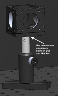 Mounting a second filter cube to a TR2 post and securing it in a PH2 post holder will provide the illuminator stability and allow you to expand your microscope for two colors later in the class.
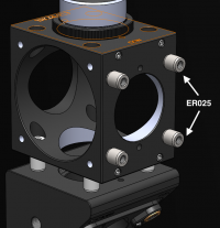
 - Use the tiny 1/4" cage rods (ER025) to connect the two C6W cages together.
 Use ER025 cage rods to connect two cage cubes.
- Mount the green excitation filter (EX1: Chroma Technologies ET550/20) in a 1/2" lens tube (SM1L05). Use two retaining rings like you did in Assignment 1 to mount your 25 mm lens for the trans illuminator.
- Mount the aspheric lens (L4) in a 1/2" lens tube (SM1L05). The 20 mm asphere (L4) looks very similar to the 25 mm plano convex lenses used previously, so make sure to label it appropriately.
- Use some plastic pipe as a sleeve around the bright green LED to protect your eyes.
 Use plastic pipe to protect your eyes from the bright LEDs.
- The dichroic mirror should already be mounted to a (B4C) platform using an FFM1 clamp. Insert the B4C platform into the cage cube (C6W). Be careful not to get fingerprints on the mirror.
- The first surface of the dichroic should face the excitation source.
- Some dichroics have an arrow indicating the first surface. If not, to ascertain which surface has the coating, watch the reflection of a corner of a piece of lens paper as it touches the mirror. On the first surface, the corner and its reflection will appear to touch. Held the other way, the corner and its image will appear a few millimeters apart.
-
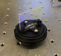 Dichroic mirror mount
 - Ask an instructor for help if you need to clean a dichroic mirror or barrier filter. Dichroics have delicate, exposed coatings and must be cleaned with extra care.
- The first surface of the dichroic should face the excitation source.
- Use four black, plastic #4/40 screws to hold the dichroic mount (B4C) on the cage cube (C6W).
- Tighten the screws enough so that the cube optic mount holds its adjustment, but can still be rotated.
- Cover the back open port of the C6W cage cube to prevent stray light from getting to your camera.
- Insert the emission filter into the emission path of your microscope (between the mirror and the tube lens). In the later part of the semester, we will add a second color LED to our microscope. The particular emission filter we'll use will work with either green or blue excitation.


Align the illumination path
- Use the lowest possible LED current when aligning. Make sure to use some plastic pipe as a sleeve around the LED to reduce stray light, and to cover the back of the C6W cube with electrical tape. Don't hesitate to ask an instructor for help during the alignment process.
- Adjust the dichroic mirror DM so that the beam will enter the middle of the objective lens.
- Remove your objective and cover the opening with an opaque screen (i.e. a kimwipe or lens paper).
- Connect your LED to the power supply. Adjust the current limit to zero, and the voltage to about 6V, and then enable the power. Gently turn up the LED power until the green light turns on. This should be less than 0.1A. (Never exceed 1A of current through these LEDs.)
- Rotate the B4C platform holding the dichroic mirror until you see some light hitting your screen. Continue rotating until the pattern is centered. You may also need to use the adjustment screws on the B4C platform to center the beam in both X and Y.
- Replace the objective.
- Use a fluorescence reference slide maximize the illumination intensity and center the field of view.
- Start up the UsefulImageAcquisition tool and set the exposure to an appropriate level.
- Bring the reference slide approximately into focus.
- Use the bottom mirror (not the dichroic) to center the illumination on the field of view of the camera. Tip: Check the "Stretch Contrast" box on the software to highlight the bright and dark regions of the image.
- Using the image histogram as your guide, rotate the dichroic mirror until the intensity is maximized. If necessary, you may also need to adjust the tilt of the mirror using the adjustment screws on the B4C base.
- Next align the position of the LED relative to its collimating lens. Loosen the set screws holding the LED in place, and slide the LED assembly forward and backward along the cage rods until the intensity is maximized (again, use the histogram to gauge the intensity values).
- Once you've found the optimal LED position, re-tighten it's set screws. You may need to re-check the dichroic mirror alignment now that you have altered the LED position.
- Finally, if necessary, readjust the bottom mirror's alignment to center the illumination on the field of view of the camera (again, stretching the contrast is helpful here).
Fluorescence imaging

In this part of the lab, you will make images of fluorescent microspheres and correct them for nonuniform illumination. In order to do the correction, you will need a reference image and dark image in addition to the image of the sample.
- Read this page to learn about the flat-field correction.
- Reference images: Take the reference image as close as possible in time to the sample images. Don't make any adjustments to your microscope between capturing the reference image and the sample image. For example, every time you move a mirror or re-align the laser, you will change the illumination profile and you must take a new reference. Adjusting the camera exposure and gain between recording the reference and sample images is okay.
- Dark images: Each time you record an image (reference or sample), make sure to take a corresponding dark image using the EXACT SAME camera settings (i.e. use the exact same Exposure Time and Gain settings you had chosen for your reference/sample image). This is the only valid way to subtract the correct dark value from your reference/sample image. Use 12-bit imaging mode to get the best results.
- Read through this page to refresh you memory on saving in MATLAB. We recommend using the save command to save data as a .mat file that you can load back into MATLAB later. This makes it easy to reanalyze your images if necessary. You could also save in an image file format with imwrite. Convert the image to 16-bit, unsigned integer format with the correct range before saving.
Take images
- Record a reference image
- Using a low LED intensity, take an image of the reference slide with the 40X objective.
- Turn off the LED illumination and record a dark image (without changing any camera settings!)
- Use MATLAB to generate a histogram of each image to be certain that the image is exposed correctly.
- Record fluorescence images of the following two samples:
- 0.84 μm beads and a corresponding dark image
- 3.26 μm beads and a corresponding dark image
- Keep in mind:
- You may need to increase your LED intensity by increasing the current limit on the power supply. Never allow the current go above 1A!
- For each sample, remember to make sure the image is exposed correctly, and to take a corresponding dark image.
- Adjust the gain (to zero) and increase the exposure of the camera to get the best picture.
Flat field correction
- Perform flat-field correction on the images.
- Divide the image by a normalized version of your reference image minus the dark image (see this page for more detail).
- Tip: If all your images are appearing dark in MATLAB you probably have not rescaled your image properly. Read through the displaying images section of this page if you need a refresher.
| |
|
- Overview
- Part 1: Noise in images
- Part 2: Fluorescence microscopy
- Part 3: Build an epi-illuminator for your microscope