Optical Microscopy Part 1: Brightfield Microscopy
Overview of Week 1
The microscope should be built in two stages. First, build a white-light inverted microscope. Verify its alignment and magnification.
Readings and resources
Strongly suggested
Optical microscopy
- From Nikon MicroscopyU
- Conjugate planes in optical microscopy Includes transmitted and reflected (epi) illumination.
- Snell's law
- Resolution
Microscope design
Your microscope will be capable of two types of illumination: transmitted bright field and epi-fluorescence. It is probably easiest to design the trans illumination microscope first and then add a fluorescence capability.
Magnification
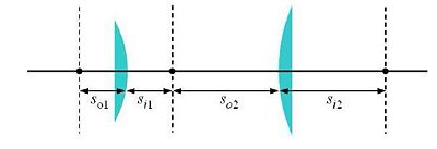
One of the simplest microscope consists of two lenses arranged in a 4-f configuration (as shown in the figure).
Bright field transmitted microscopy is the simplest and most common optical microscopy method. In this technique, photons from an illuminator pass through the sample, where the may be absorbed, diffracted, or refracted. (The sample us usually mounted on a glass slide.) An objective lens on the opposite side of the sample collects the light. Most modern objective lenses produce collimated light, which is focused by a tube lens to form an image.
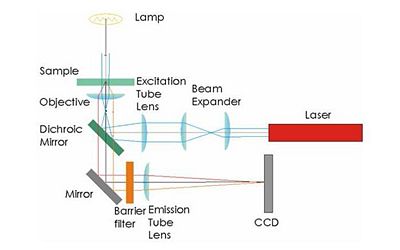
Illumination for epifluorescence microscopy reaches the sample through the objective lens — from the same side of the sample that is observed. Epi-fluorescence microscopy is normally used on samples that have been labled with a fluorescent molecule called a fluorophore. The (narrowband) illumination wavelength must match the absorption characteristic of the fluorophore. After becoming excited by a photon from the illuminator, fluorophores emit photons with a longer wavelength. A dichroic mirror in the microscope reflects the illumination wavelength but allows the emitted photons to pass through.
An example microscope made by the instructors will be available in the lab for you to examine. Feel free to make improvements on this design. Stability will be crucial for the particle tracking experiments. The required specification will be achieved through good design and careful construction — not by mindlessly overtightening screws.
Some elements must be positioned precise distances apart; other distances are not critical. Use ray-tracing to determine when this is the case.
Bright field transmitted illumination imaging
Sketch out a rough design for your microscope on paper. Begin with the bright field illumination path.
Note:
- The Nikon objective lenses are designed to be paired with a 200 mm tube lens.
- Assume that the objectives behave as ideal plano-convex lenses.
- Fine focusing will be achieved by adjusting the height of the sample stage.
- Start the alignment with a 10× objective but progress to 40× and 100×.
- Use the red LED illuminators for bright field transmitted light imaging.
- Put a quick connect in your design such that the camera CCD will end up 200mm from the back focal plane of the objective. Remember that the CCD is recessed inside the opening of the camers.
Microscope components
Rigid optical construction
The structure of your microscope will be built from a combination of cage and lens tube components from ThorLabs. (See the ThorLabs online catalog for more details. Print catalogs are available in the lab.) Be sure you understand how to use cage cubes (C4W), cube optic mounts (B5C), and kinematic mounting plates (B4C). Please ask about any components you are not sure how to use.
An example microscope put together by the instructors will be available in the lab for you to look at. Feel free to make improvements on this design. Stability will be crucial for the particle tracking experiments. This will be achieved through good design and careful construction — not by mindlessly overtightening screws.
Simple lenses
Plano-convex spherical lenses are available with focal lengths of 25, 50, 75, 100, 125, 150, 175, and 200 mm. It is best to mount most optics in short (0.5" or 0.3") lens tubes. It is acceptable to mount a lens between the end of a tube and a tube ring or between two tube rings. In most cases, the convex side of the lens faces toward the collimated beam; the planar side goes toward the convergent rays. Plano-concave lenses with focal lengths of -30 and -50 are also available.
- Advice: Some students in the past have had difficulty with the Three of These Things game. Verify all optics before you use them by measuring the focal length with a ruler.
As you install lenses into your microscope, put a piece of tape on the lens tube showing focal length and orientation. This will help you both during constructino and put-away. Save the lens storage boxes and return components to the correct boxes when you are done.
Handle lenses only by the edges. If a lens is dirty, first remove grit with a blast of clean air or CO2. Clean the lens by wiping with a folded piece of lens paper wetted with a drop of methanol. (Do not touch the part of the tissue you use for cleaning with your fingers.) In some cases, it may be helpful to hold the folded lens tissue in a hemostat. Ask an instructor if you need help.
Objective lenses
Please see the Nikon Introduction to Microscope Objectives at their excellent MicroscopyU website.
There are three objective lenses available in the lab: a 10×, a 40×, and a 100×. All of these are designed for a 200 mm tube lens. An adapter ring converts the objective mounting threads to the SM1 threads used by the lens tube system.
- The back focal plane (BFP) of the objective coincides with the rear of the objective housing. This is equivalent to the focal plane of a simple lens.
- Working distance (WD) is the distance between the front end of the objective and the sample plane (when the sample is in focus). Generally, the higher the magnification, the lower the working distance.
- The 100× objective is designed to be used with immersion oil, which provides an optical medium of pre-determined refractive index (n = 1.5). When using the 100× objective, place a drop of oil on it. Bring the drop in contact with the slide cover glass. After use, clean off excess oil by wicking it away with lens paper. Do not put samples away dirty. It is not necessary to use immersion oil for thin samples such as the Air Force Target or Ronchi Ruling.
Sample stage
Precision Newport X/Y/Z stages mounted on a post are available at each lab station. The stage setup is top-heavy. Avoid accidents by ensuring that the post base is always attached to an optical breadboard or table. Return the stage to the lab station when you are done with it.
The z-axis adjustment of the sample stage provides fine focusing.
CCD camera
The microscope you will build does not have an eyepiece for direct visual observation. Instead, images will be captured with a CCD camera (Allied Manta G032B). Its monochrome (black and white) sensor contains a grid of 656×492 square pixels that measure 7.4 μm on a side. An adapter ring converts the C-mount thread on the camera to SM1.
Bright field calibration
Make images the following samples using the three different objectives (10×, 40×, and 100×):
- The smallest line pair on the Air Force imaging target 1951 or 1963A (find datasheets on the web)
- A slide of 7 μm, 3.2 μm or 1 μm silica spheres
- Ronchi ruling - a periodic pattern containing 600 line-pairs per mm
Can you see all these samples? What is the magnification of the microscope and the size of its field of view? Is it what you expected?
Fluorescence imaging
Now sketch a layout that includes both the bright field and fluorescence illumination paths.
- Use a dichroic to direct the laser illumination toward the sample and to pass the emitted (fluorescent) light back through to the CCD.
- The barrier filter removes any light from the illumination laser that was not reflected by the dichroic.
- During fluorescent imaging, you will not use the bright field illuminator. Bright field capability is useful for first visualizing the sample and viewing what features are in the field of view. Your design should retain the ability to do both white light and fluorescent visualization.
- Verify your design with one of the lab instructors before beginning construction.
Fluorescence illumination
The fluorescent illumination source is a 5 mW, λ=532 nm green laser pointer. Do not begin working with the laser until you are familiar with laser safety procedures. If you missed laser safety training, please see an instructor.
- Wear the correct laser safety eyewear at all times — even when your laser is not on — since other groups may be using theirs.
- Make sure the laser warning light outside the main door to the lab is flashing before you turn on a laser.
- Never point the laser toward other people.
- Laser light can emerge from the top of the objective lens. Never put your face directly above the objective.
Beam expansion
Collimated light comes out of the laser pointer. The light should also be collimated when it reaches the sample (Kohler illumination). In order to provide a good image, the laser light should illuminate most of the field of view. The beam emerging from the laser pointer (abuot 1.1 mm) may not be wide enough. This means that the laser beam will need to be expanded. What expansion factor should you use for a 40× objective? The design of the beam expander is a tradeoff. Overexpansion will decrease the light intensity at the sample and may not give you enough power for imaging. Underexpansion will result in very uneven illumination.
Dichroic mirror and barrier filter
The fluorophores we will emit light in the orange-red region of the visible spectrum (550-600 nm) when excited by the 532 nm green laser.
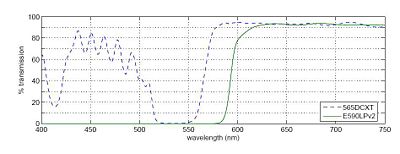
In any fluorescence system, a key concern is viewing only the emitted fluorescence photons, and eliminating any background light, especially from the illumination source. Two optical elements address the problem. A dichroic mirror passes light of one wavelength, and reflects light of another. The transmission spectrum for the 565DCXT dichroicis shown in Fig. 3. A barrier filter blocks a particular spectral region. We will use the E590LPv2 barrier filter.
Figure 1 shows the tranmittance of the dichroic mirror and barrier filter over a range of wavelengths. The barrier filter is essential for high-sensitivity fluorescence imaging. It will pass the red light from the LED in the illuminator for bright field imaging as well as the fluorescence photons.
Experiment 2:Fluorescence characterization and imaging
You have the following samples available for imaging using both 40× and 100× objectives:
- A fluorescence reference slide
- A sample slide with 4 μm red-fluorescent beads (modified with Nile Red dye, peak excitation at 535nm, peak emission at 575nm).
Imaging tasks:
- Use a fluorescence reference slide to center the field of view and to optimize the uniformity of illumination. Take an image of this. Use the histogram display of the camera software to be certain that the image is not overexposed.
- Take an image of the fluorescent beads. Perform flat field correction on the image(i.e. divide the image by the normalized reference image). Compare what you see before and after flat field correction.
- Image a stained onion slide in bright field and fluorescent contrast. Do a flat-field correction on the fluorescent image. Overlay the fluorescent image on top of the bright field image.
- Make an image of the PSF slide. This slide consists of 190nm fluorescent beads plus some 1μ beads to help focus in bright field contrast.
FM-dye reference[1]
Lab manual sections
- Optical Microscopy Week 1: Build a brightfield microscope
- Optical Microscopy Week 2: Add a fluorescence branch
- Optical Microscopy Week 3: Experiments
References
- ↑ S. Bolte, C. Talbot, Y. Boutte, O. Catrice, N. D. Read, B. Satiat-Jeunemaitre. FM-dyes.pdf FM dyes as experimental probes for dissecting vesicle trafficking in living plant cells. Journal of Microscopy 214(2): 159-173 (May 2004).
Lab manual sections
- Optical Microscopy: Construction of a microscope
- Optical Microscopy: Construction of a microscope#Fluorescence imaging
- Optical Microscopy Week 3: Experiments
References


