Geometrical optics and ray tracing
Reflection and refraction
When incident light reaches an interface between two optical media, it can be
- reflected, partly or totally,
- scattered in random directions,
- refracted and thus entering the second medium, and/or
- absorbed partly.
We will limit our seminal discussion of basic geometrical optics to cases where interfaces are non-absorbant and smooth (as opposed to uneven) surfaces giving rise to specular (as opposed to diffuse) reflection and refraction.
Reflection at a boundary
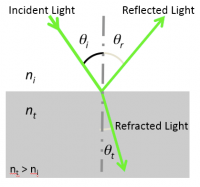
- The law of reflection states that the angle θr the reflected ray makes with the normal to the surface is equal to the angle θi the incident ray makes with this normal. Incident and reflected rays are in the same plane.
- $ \theta_i = \theta_r $
- The law of reflection applies to plane and curved (e.g. spherical) interfaces.
Refraction at a plane boundary
Index of refraction
- The index of refraction $ n $ of a transparent optical medium is defined as the ratio of the speed of light in vacuum, $ c $, by the speed of light in the medium, $ v $.
- $ n = c / v $
Snell's law of refraction
- Light incident at an interface between two media of distinct indices of refraction will be partly reflected back into the first medium and partly transmitted to the second medium, or refracted according to the Snell-Descartes law:
- $ n_i\ \sin \theta_i = n_t\ \sin \theta_t $
- with θ the angle measured from the normal of the boundary, $ n $ the refractive index (which is unitless) of the medium, and the subscripts $ i $ and $ t $ referring to the incident and transmitted light, respectively.
- Snell's law implies that light passing from a medium of lower index to a higher index of refraction ($ n_t > n_i $) bends toward the surface normal ($ \theta_t < \theta_i $), whereas light traveling from a higher index to a lower index of refraction bends away from the normal.
Critical angle and total internal reflection
- From Snell's law of refraction ensues the existence of a critical angle $ \theta_c $ for the incident light ray at which it gets bent by 90o at the boundary and thus continues traveling along the interface between the two media. Beyond $ \theta_c $ total internal reflection takes place.
- Recalling that $ \sin (90^o) = 1 $, one can derive
- $ \theta_c = \sin ^{-1} \left ( {n_t \over n_i} \right ) $
- The phenomenon of total internal reflection is the principle of light transmission via optical fibers, whose core medium is cladded by a distinct medium of lower index of refraction.
Refraction at a spherical boundary
Gaussian optics assumptions
The lens formulas and ray tracing techniques we'll be using will rely on the first-order or Gaussian optics approximations:
- Paraxial (or small-angle) approximation:
- $ \theta \approx \sin\ \theta \approx \tan\ \theta $
- $ \cos\ \theta \approx 1 $
- (These relations obtained from the first-order terms of the polynomial expansions of $ \sin \theta = \theta - {\theta^3 \over {3!}} + {\theta^5 \over {5!}} - ... $ and $ \cos \theta = 1 - {\theta^2 \over {2!}} + {\theta^4 \over {4!}} - ... $ are accurate to 1% if $ \theta < 10^o $.)
- Thin-lens approximation:
- $ R << S_o,\ S_i $
- with $ R $ defined as the radius of curvature of the lens, $ S_o $ as the distance between the lens and the object, and $ S_i $ the distance between the lens and the image.
- The paraxial and thin-lens assumptions are engineering approximations that allow you to quickly and intuitively understand most optical systems using a simple set of ray tracing rules.
- Deviations from these assumptions result in optical aberrations.
Image position and magnification
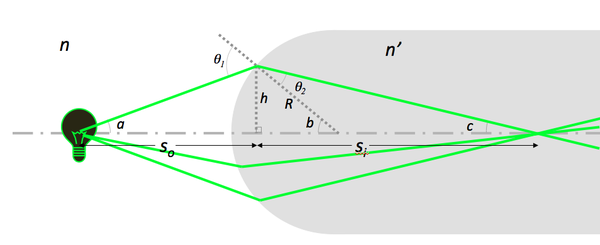
- Under Gaussian optics conditions, Snell's law predicts the image position of an object formed by a lens:
- $ n\ \sin \theta_1 = n'\ \sin \theta_2 $
- $ \sin \theta_1 \approx \sin a + \sin b \approx {h \over S_o} + {h \over R} $
- $ \sin \theta_2 \approx \sin b - \sin c \approx {h \over R} - {h \over S_i} $
- $ {n \over S_o} + {n' \over S_i} = {(n'\ - n)\over R} $
- Magnification by the lens is:
Note that
- Si does not depend on the angle $ a $.
- Light coming from a point on the filament passes through a point after refraction.
- Hecht matrix for thick lens.
| a) $ S_o > {n\ R \over (n'\ - n)}\ \Rightarrow S_i > 0 $ , | b) $ S_o = {n\ R \over (n'\ - n)}\ \Rightarrow S_i \to + \infty $, | c) $ S_o = {n\ R \over (n'\ - n)}\ \Rightarrow S_i < 0 $ |
Lenses
Lens maker formula
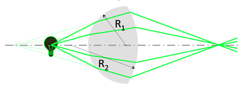
A simple lens consists of two spherical interfaces. Its focal length $ f $ is given by the lens maker formula:
- $ {1 \over S_o} + {1 \over S_i} = {1 \over f} = {(n'\ - n) \over n} \left ( {1 \over R_1} - {1 \over R_2} \right ) $
| Bi-convex lens | Plano-concave lens |
|---|---|
- Use the image from the first refraction as the object for the second.
- Note the sign convention for the second surface: $ R_2 $ < 0 for a convex lens, and $ (n'\ - n) $ has opposite sign.
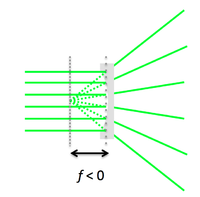
- Concave lens: the lens maker formula holds for $ R_1 $ < 0.
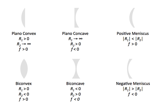
Types of spherical lenses
To minimize spherical aberrations, the general rule is to position the curved side of the lens toward the collimated/straight light.
f-number f/stop and numerical aperture
numerical aperture as light-gathering power of lens (e.g. objective in microscope)
aperture and stop (camera, field of view)
Ray Tracing
Principles
- The paraxial and thin-lens assumptions are engineering approximations that allow you to quickly and intuitively understand most optical systems using a simple set of ray tracing rules:
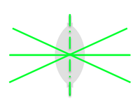
| Rays passing through the optical center of a lens continue in a straight line | |
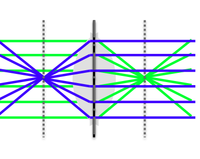
| Rays traveling parallel to the optical axis pass through the focal point after refraction and vice versa | |
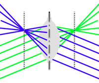
| Parallel rays pass through the same point in the focal plane after refraction and vice versa |
Objects and images
Imaging with a lens
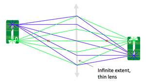
- Imagine the object is made up of many point sources. After refraction, all the rays from a single point in the object plane reach the same location in the image plane. This forms a real, inverted image. By similar triangles, magnification is equal to the ratio of distances.
A 4 f or compound microscope
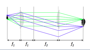
- A 4 f microscope is made of two positive lenses, placed at the sum of their focal lengths apart.
- An object (sample) placed in the focal plane of the first lens gets magnified by the ratio of focal lengths, $ f_2 / f_1 $.
The eye as a lens
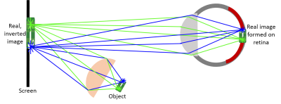
| The eye’s optical system focuses the light from each point of the object on to a point on the retina to create an image. | |
| |
| You can also view a real image directly. In an optical system the image of a lens acts like the object of the next. | |
You can observe a virtual image.
|

