Difference between revisions of "Geometrical optics and ray tracing"
(→Spherical lenses and image formation) |
|||
| Line 82: | Line 82: | ||
====Object and image positions==== | ====Object and image positions==== | ||
| − | |||
Now, with our Gaussian optics assumptions, we can use Snell's law to predict the image position of an object, formed by a spherical interface (refer to light bulb image above): | Now, with our Gaussian optics assumptions, we can use Snell's law to predict the image position of an object, formed by a spherical interface (refer to light bulb image above): | ||
:<math> n\ \sin \theta_1 = n'\ \sin \theta_2 </math> | :<math> n\ \sin \theta_1 = n'\ \sin \theta_2 </math> | ||
| Line 90: | Line 89: | ||
Note that equation does not depend on angle a! | Note that equation does not depend on angle a! | ||
| + | Massaging this equation gives three possible relationships between <math>S_i</math> and <math>S_o</math>: | ||
| + | |||
| + | {| class="wikitable" | ||
| + | !colspan="3"|[[Image: 20.309 130819 RefSphere2.png|frameless|center|750px]] | ||
| + | |- | ||
| + | |a) '''Light converges''' | ||
| + | <math> S_o > {n\ R \over (n'\ - n)}\ \Rightarrow S_i > 0</math> , | ||
| + | |b) '''Light is collimated''' | ||
| + | <math> S_o = {n\ R \over (n'\ - n)}\ \Rightarrow S_i \to + \infty</math>, | ||
| + | |c) '''Light diverges''' | ||
| + | <math> S_o < {n\ R \over (n'\ - n)}\ \Rightarrow S_i < 0</math> | ||
| + | |} | ||
| + | |||
| + | Note the sign convention is that if <math>S_i < 0 </math>, the light diverges, and a virtual image is formed at a distance <math>|S_i|</math> in front of the lens, on the same side of the lens as the light source (virtual images will be discussed more in a following section). | ||
===Lenses=== | ===Lenses=== | ||
| Line 111: | Line 124: | ||
====Image formation==== | ====Image formation==== | ||
| + | We could put image formation here instead of at one spherical boundary...and use the lens equation to show diverging and converging | ||
| − | |||
| − | |||
| − | |||
| − | |||
| − | |||
| − | |||
| − | |||
| − | |||
| − | |||
| − | |||
| − | |||
| − | |||
| − | |||
| − | |||
==Ray tracing== | ==Ray tracing== | ||
| Line 147: | Line 147: | ||
===Image formation=== | ===Image formation=== | ||
| − | When an object gives off its own light (like a light bulb) or is illuminated, we can imagine that the object is made up of many point sources, where each point on the object is emitting or scattering light in all directions. After refraction, all the rays from a single point in the object plane reach the same location in the image plane, forming an image. | + | When an object gives off its own light (like a light bulb) or is illuminated, we can imagine that the object is made up of many point sources, where each point on the object is emitting or scattering light in all directions. After refraction, all the rays from a single point in the object plane reach the same location in the image plane, forming an image. The image can be either real or virtual. |
| − | The image can be either real or virtual. A '''real image''' is one that can be seen if you put a screen on the image plane. A '''virtual image''' cannot be seen if a screen is at the image plane since there is no place the rays actually come together; it needs another lens (such as your eye) in order to view it. More examples of real and virtual images are described in a following section (link). | + | |
| + | |||
| + | A '''real image''' is one that can be seen if you put a screen on the image plane. A '''virtual image''' cannot be seen if a screen is at the image plane since there is no place the rays actually come together; it needs another lens (such as your eye) in order to view it. More examples of real and virtual images are described in a following section (link). | ||
[[Image: 20.309 130909 ImagingWithLens.png|left|thumb|400px]] | [[Image: 20.309 130909 ImagingWithLens.png|left|thumb|400px]] | ||
Revision as of 14:04, 1 July 2015
Overview
Light is an extraordinarily complicated, three dimensional, time dependent phenomenon. Completely describing a light field requires a function that quantifies the intensity, phase, wavelength, and propagation direction of light at every point in space. Needless to say, it can be difficult to conceptualize a light field. Fortunately, there is a simplified model of light called ray optics that works well in situations where the objects that interact with a light field are much larger than the wavelength of the light.
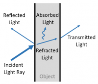
Ray optics (a.k.a. geometric optics) simplifies a light field by turning it into a collection of lines that point in the direction of propagation. The lines begin at a source and go straight, until an interaction between light and matter causes a change. When a ray encounters an object, it may be:
- Reflected
- Refracted (the light is bent by the material properties of the object)
- Absorbed (often turned into thermal energy)
- Transmitted
- Scattered in a random direction
- Or some combination of the above.
The simplifications of ray optics provide a very good way to understand systems of lenses, mirrors, filters, and illumination sources. In many cases, ray optics can elucidate the function of a complicated optical system with just a few lines, triangles, and simple rules. Of course, the simplicity of ray optics comes at a cost. Ray optics glosses over important details like diffraction and interference. Because the fine details are omitted, ray optics alone does not provide insight into detailed performance characteristics like resolution.
This page introduces ray optics and discusses distortions called optical aberrations that occur in situations where one or more of the simplifying assumptions fail. Diffraction and resolution are discussed on a separate page.
The systems of optical components that we will consider in 20.309 have smooth surfaces made of non-absorbent materials. Their behavior is predominantly governed by reflection and refraction, so we won't spend a lot of time on scattering and absorption for now.
Relationship between light rays and waves
Rays point in the direction of propagation.
| File:Snells law wavefronts.gif |
| Representation of the field generated by a point source. The blue circles indicate peaks of the electric field at one time in a plane that includes the source. A small distance below the source, there is an interface to a medium with higher refractive index. Light propagates at a slower speed in the higher-index medium. An example ray (red line) is drawn perpendicular to the axis of propagation. The ray bends at the interface between the two media. |
Relationship of manta rays to waves
Not so much. But manta rays are really cool.
Reflection and refraction
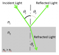
When light reflects, the angle of the reflected ray is equal to the angle of the incident ray: $ \theta_r=\theta_i $. Both angles are measured relative to a vector normal to the surface. Incident and reflected rays are in the same plane.
Light incident at an interface between two media will be partly reflected back into the first medium and partly transmitted to the second medium. The speed of light will be different in the two media based on their material properties. The index of refraction $ n $ for each material is defined as the ratio of the speed of light in vacuum, $ c $, by the speed of light in the medium $ v $. More succinctly, $ n = c / v $. When the light changes speed in the second medium, its direction of propagation also changes. This phenomenon is known as refraction. The transmitted light propagates at an angle described by Snell's law:
- $ n_i\ \sin \theta_i = n_t\ \sin \theta_t $
with θ the angle measured from the normal of the boundary, $ n $ the refractive index of the medium (which has no units), and the subscripts $ i $ and $ t $ referring to the incident and transmitted light, respectively.
Note that Snell's law implies that light passing from a medium of lower index to a higher index of refraction ($ n_t > n_i $) bends toward the surface normal ($ \theta_t < \theta_i $), whereas light traveling from a higher index to a lower index of refraction bends away from the normal. Remember, a higher index means a lower velocity of light in the medium.
An example of using Snell's law: critical angle and total internal reflection
- Snell's law includes the concept of a critical angle $ \theta_c $ for the incident light ray. As the angle of the incident ray approaches $ \theta_c $, the angle $ \theta_t $ approaches 90o. Beyond $ \theta_c $, total internal reflection takes place. In this regime the ray obeys the rules of reflection above.
- Recalling that $ \sin (90^o) = 1 $, one can derive
- $ \theta_c = \sin ^{-1} \left ( {n_t \over n_i} \right ) $
- All fiber optic communication takes advantage of the phenomenon of total internal reflection. The core medium of a fiber is covered by another medium with a lower index of refraction, called the cladding. Thus if light enters the fiber at an angle less than $ \theta_c $, and if the fiber is not bent too far, then the entering light will emerge at the end of the fiber minus only losses in the fiber, plus losses due to other practicalities of the real world of course.
Spherical lenses and image formation
Refraction at a spherical boundary
Lenses are one of the most common components of optical instruments. There are many types of lenses, but the most common ones are spherical lenses, which have curved surfaces. To better understand how they manipulate light, let's consider what happens to light at a spherical boundary.
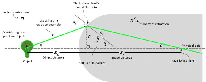
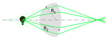
The figure below demonstrates how light rays from a point on an object (the light bulb) can focus to a point after passing through a spherical boundary. The depicted angles and defined lengths can be used to calculate where the light will focus. Even though we only pick a few rays to look at, remember that each point on the object acts as a point source where there are light rays emanating from them in all directions.
Gaussian optics assumptions
As we begin to deal with multiple boundaries, it can become complicated to solve many geometric equations to find where the image will form. In order to make more tractable calculations for us to use when designing our optical systems, we rely on a few first-order, or Gaussian optics, approximations:
- Paraxial (or small-angle) approximation:
- Assumes that light rays make a small angle with the principal axis (a straight line perpendicular to the center of the curved surface)
- $ \theta \approx \sin\ \theta \approx \tan\ \theta $
- $ \cos\ \theta \approx 1 $
- (These relations are obtained from the first-order terms of the polynomial expansions of $ \sin \theta = \theta - {\theta^3 \over {3!}} + {\theta^5 \over {5!}} - ... $ and $ \cos \theta = 1 - {\theta^2 \over {2!}} + {\theta^4 \over {4!}} - ... $ and are accurate to 1% if $ \theta < 10^o $.)
- Thin-lens approximation:
- $ R << S_o,\ S_i $
- with $ R $ defined as the radius of curvature of the lens, $ S_o $ as the distance between the lens and the object, and $ S_i $ the distance between the lens and the image.
- These paraxial and thin-lens engineering approximations simplify most optical systems by enabling the use of a short set of ray tracing rules for spherical lenses. These rules reduce many optics problems to more intuitive geometry problems.
- Deviations from these assumptions result in optical aberrations.
- More on thick lenses can be found in the book 'Optics' by Eugene Hecht (Addison-Wesley, 2002, ISBN 0805385665).
Object and image positions
Now, with our Gaussian optics assumptions, we can use Snell's law to predict the image position of an object, formed by a spherical interface (refer to light bulb image above):
- $ n\ \sin \theta_1 = n'\ \sin \theta_2 $
- $ \sin \theta_1 \approx \sin a + \sin b \approx {h \over S_o} + {h \over R} $
- $ \sin \theta_2 \approx \sin b - \sin c \approx {h \over R} - {h \over S_i} $
- $ {n \over S_o} + {n' \over S_i} = {(n'\ - n)\over R} $
Note that equation does not depend on angle a!
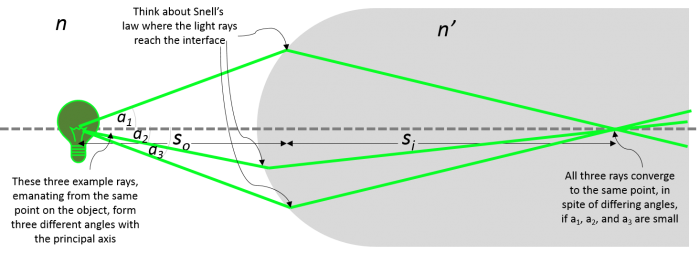
Massaging this equation gives three possible relationships between $ S_i $ and $ S_o $:
| a) Light converges
$ S_o > {n\ R \over (n'\ - n)}\ \Rightarrow S_i > 0 $ , |
b) Light is collimated
$ S_o = {n\ R \over (n'\ - n)}\ \Rightarrow S_i \to + \infty $, |
c) Light diverges
$ S_o < {n\ R \over (n'\ - n)}\ \Rightarrow S_i < 0 $ |
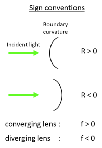
Note the sign convention is that if $ S_i < 0 $, the light diverges, and a virtual image is formed at a distance $ |S_i| $ in front of the lens, on the same side of the lens as the light source (virtual images will be discussed more in a following section).
Lenses
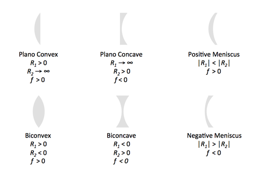
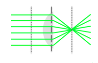
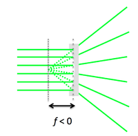
A simple lens consists of two spherical interfaces of radii of curvature $ R_1 $ and $ R_2 $. Its focal length $ f $ is where the image is formed when an object is at infinity.
Types of spherical lenses
A practical note: to minimize spherical aberrations, the general rule is to position the curved side of the lens toward the collimated/straight light.
Lens maker's formula
Using the equation we derived earlier to find the image position after light passes through one spherical boundary, we can apply the formula twice--once for each spherical boundary of a simple lens, to calculate where the image will form after light passes through the entire lens. If we maintain our thin lens approximation, and take the image from the first refraction as the object for the second one, we can derive the lens maker's formula (see this page <--link for details):
This formula shows us that the focal length of the lens is a characteristic of the lens, based on its radii of curvature and relevant indices of refraction.
Image formation
We could put image formation here instead of at one spherical boundary...and use the lens equation to show diverging and converging
Ray tracing
Based on what we've learned about how light is redirected when passing through lenses, we can come up with a set of rules to simplify our analysis of optical systems. With the technique of ray tracing, we can figure out where images are formed, whether they're upside down, magnified, etc.
Principles
Image formation
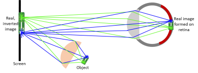
When an object gives off its own light (like a light bulb) or is illuminated, we can imagine that the object is made up of many point sources, where each point on the object is emitting or scattering light in all directions. After refraction, all the rays from a single point in the object plane reach the same location in the image plane, forming an image. The image can be either real or virtual.
A real image is one that can be seen if you put a screen on the image plane. A virtual image cannot be seen if a screen is at the image plane since there is no place the rays actually come together; it needs another lens (such as your eye) in order to view it. More examples of real and virtual images are described in a following section (link).
Ray tracing examples
Objects and images
Imaging with a lens
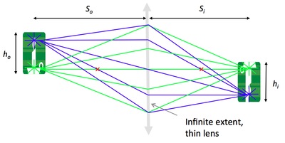
Imagine the object is made up of many point sources. After refraction, all the rays from a single point in the object plane reach the same location in the image plane. This forms a real, inverted image.
Magnification
By similar triangles, magnification is equal to the ratio of distances to the lens:
$ M = {h_i \over h_o} = {S_i \over S_o} $
You will verify this equation through the Optics Bootcamp exercise of the first problem set.
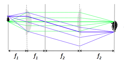
A 4 f or compound microscope
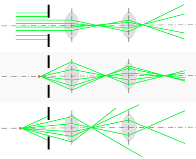
- A 4 f microscope is made of two positive lenses, placed at the sum of their focal lengths apart.
- An object (sample) placed in the focal plane of the first lens gets magnified by the ratio of focal lengths, $ f_2 / f_1 $.
- It is left as an exercise to the reader to show that the two lenses do not need to be separated by $ f_1 + f_2 $. Hint: Make clever use of Rule 3.
The eye as a lens
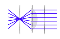
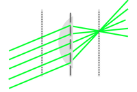
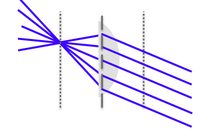
| |
| |
| |
You can observe a virtual image.
|
| Bi-convex lens | Plano-concave lens |
|---|---|
Aperture and field stops
Aperture stop and image brightness
- The aperture stop of an imaging system is the optical element that limits angle of rays passing through the system from a source on the optical axis.
- For an off-axis object, the chief ray is the ray that passes through the center of the aperture stop, and the marginal rays are those that pass through the edge of the aperture stop.
- The size of the aperture stop determines the light-gathering capability of an instrument, and thus the brightness (or irradiance in W/m2) of its images.
- Typically in a microscope, as opposed to a photographic camera, the aperture stop will be the objective lens rather than an aperture before the lens as shown here.
Numerical aperture
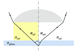
- The numerical aperture (NA) is another important measure that characterizes the light-gathering power of a lens.
- $ NA = n\ \sin \alpha $
- where $ n $ is the index of refraction of the medium between the object (sample) and the lens and $ \alpha $ is the half-angle defined by the limiting ray. The limiting ray is is the last ray not blocked by any aperture.
- An oil-immersion objective lens will thus have a greater NA than an air-immersion objective lens ($ n_{oil} > n_{air} $ and $ \alpha_{oil} > \alpha_{air} $; indeed, little refraction occurs at the glass-oil interface where $ n_{oil} \approx n_{glass} $). Notice the much smaller angle of the limiting ray (drawn, but not labeled, near the point of origin in the diagram) in the case of air-immersion lens.
Field stop and field of view
- The field stop is the optical element that blocks off-axis rays passing through the center of the aperture stop (i.e. the chief rays).
- The field stop determines how much of the object can be viewed, in other words: the field of view of the imaging system.
- In your 20.309 microscope, the field stop will be the CCD camera.
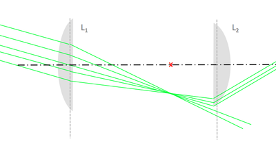
- A finite-size lens can also act as a field stop. Below is an illustration of this vignetting effect: a cone of light rays from an off-axis object is not transmitted in its entirety, but rather partially cut off by the field stop of the system, L2's rim.
Further reading
References

