Difference between revisions of "Optical Microscopy Part 2: Fluorescence Microscopy"
MAXINE JONAS (Talk | contribs) (Creating "Optical Microscopy Part 2: Fluorescence Microscopy" page) |
MAXINE JONAS (Talk | contribs) |
(No difference)
| |
Revision as of 20:49, 12 August 2013
Contextual Background
Recommended reading
Design of a fluorescence microscope
Beam expansion
Your 20.309 microscope
Components in the 20.309 lab
Laser illumination and laser safety
The fluorescent illumination source is a 5 mW, λ=532 nm green laser pointer. Do not begin working with the laser until you are familiar with laser safety procedures. If you missed laser safety training, please see an instructor.
- Wear the correct laser safety eyewear at all times — even when your laser is not on — since other groups may be using theirs.
- Make sure the laser warning light outside the main door to the lab is flashing before you turn on a laser.
- Never point the laser toward other people.
- Laser light can emerge from the top of the objective lens. Never put your face directly above the objective.
Dichroic mirror and barrier filter
The fluorophores we use will emit light in the orange-red region of the visible spectrum (550-600 nm) when excited by the 532 nm green laser.
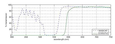
In any fluorescence system, a key concern is viewing only the emitted fluorescence photons, and eliminating any background light, especially from the illumination source. Two optical elements address the problem. A dichroic mirror reflects light of one wavelength, and passes light of another. The transmission spectrum for the 565DCXT from Chroma Technologies, which is similar to your NT47-268 dichroic from Edmund Optics, is shown in Figure 3. In contrast, a barrier filter blocks a particular spectral region extremely well. We will use the E590LPv2 barrier filter from Chroma Technologies.
Figure 3 shows the transmittance of the dichroic mirror and barrier filter over a range of wavelengths. The barrier filter is essential for high-sensitivity fluorescence imaging as it will block any reflected green light while allowing trace amount of red light from the fluorophores. It will also pass the red light from the LED in the illuminator for bright field imaging so that you can accomplish combined bright field and fluorescent imaging to help set up your sample.
Samples
You have the following samples available for imaging with both 40× and 100× objectives:
- A fluorescence reference slide
- Several types of sample slides with 4 μm or 1 μm red-fluorescent beads (several different dyes, but with peak excitation roughly 535nm, peak emission roughly 575nm)
- PSF slides with 100 nm or 190 nm red-fluorescent beads
Data sheets
Considerations to keep in mind while working
Beam expansion criteria
Collimated light comes out of the laser pointer. The light should also be collimated when it reaches the sample (Kohler illumination). In order to provide a good image, the laser light should illuminate most of the field of view. The beam emerging from the laser pointer (approximately 1.1 mm) may not be wide enough. This means that the laser beam will need to be expanded. The design of the beam expander is a tradeoff. Overexpansion will decrease the light intensity at the sample and may not give you enough power for imaging. Underexpansion will result in very uneven illumination.
- What expansion factor should you use for a 40× objective?
- Remember that the Gaussian propagation law dictates that divergence X beam waist = constant.
Barrier filter incorporation
To easily switch back and forth between bright-field and fluorescence microscopy mode, you may need to remove and add the barrier filter (BF) from your setup (this is obviously true and mandatory if your bright-field light source is a blue LED, whose transmitted light would otherwise be blocked by the E590LPv2 BF; the latter only transmits light of wavelength > 590 nm).
- Keeping in mind that barrier filters are designed to work under collimated light illumination, where do you intend to position the BF in your microscope light path?
- What wavelengths must your BF transmit?

