20.109(S21):M3D4
Contents
Introduction
As evidenced by Nagai’s work, wild-type inverse pericam is not toxic to BL21(DE3)pLysS cells. Although it is unlikely that your point mutation will dramatically change this fact, in general a novel protein may turn out to be toxic. If this is the case, only very small amounts of protein are produced before the bacteria die. Keep in mind that overexpressing a single protein may come at the expense of producing proteins needed for survival, and will most likely cause cell death eventually; however, toxic proteins hasten this demise. Aberrant toxicity can sometimes be alleviated by reducing the culture temperature (e.g., to 30 °C).
Based on its fluorescence activity, wild-type inverse pericam allows proper folding of (cp)EYFP, and based on its response to calcium, it also allows calmodulin to fold. One problem you may encounter is that your mutant proteins will no longer fold correctly. Since you made mutations in the calcium sensor part of IPC, rather than the fluorescent part, it is unlikely that your protein will destroy EYFP fluorescence. However, a common problem with misfolded proteins is the formation of insoluble aggregates, due for instance to improperly exposed hydrophobic surfaces. Proteins can be purified from these aggregates – called inclusion bodies – but the process is more labor-intensive than for soluble proteins. (The proteins must be extracted under more harsh conditions than you will use next time, then purified under denaturing conditions, before finally attempting to renature the proteins.) Inclusion bodies sometimes form simply due to very high expression of the protein of interest, causing it to pass its solubility limit. This outcome can be prevented by lowering the culture temperature, the induction duration, the amount of IPTG, or the growth phase of the bacteria.
One final point to keep in mind is that not all proteins can be produced in bacteria. Eukaryotic proteins that require post-translational modifications (such as glycosylation) for activity require eukaryotic hosts (such as yeast, or the commonly used CHO – Chinese hamster ovary – cells). Sometimes eukaryote-derived proteins will be truncated or otherwise mistranslated by E. coli due to differential codon bias; errors in translation can be prevented by providing additional tRNAs to the culture or directly to the bacteria via plasmids. Despite all this complexity, prokaryotic hosts have been plenty good enough to produce proteins for certain therapies, notably the cytokine G-CSF. This cytokine is taken by patients needing to replenish their white blood cells (e.g., after chemotherapy), and sold as Neupogen by the company Amgen.
This is it, folks! Moment of truth. Time to find out how the proteins that you worked so hard to express, purify, and test really behave. Although you should be able to produce reasonable titration curves by following the example of Nagai, the introduction/review of binding constants below may help contextualize your analysis.
Let’s start by considering the simple case of a receptor-ligand pair that are exclusive to each other, and in which the receptor is monovalent. The ligand (L) and receptor (R) form a complex (C), which can be written
$ R + L \rightleftharpoons\ ^{k_f}_{k_r} C $
At equilibrium, the rates of the forward reaction (rate constant = $ k_f $) and reverse reaction (rate constant = $ k_r $) must be equivalent. Solving this equivalence yields an equilibrium dissociation constant $ K_d $, which may be defined either as $ k_r/k_f $, or as $ [R][L]/[C] $, where brackets indicate the molar concentration of a species. Meanwhile, the fraction of receptors that are bound to ligand at equilibrium, often called y or θ, is $ C/R_{TOT} $, where $ R_{TOT} $ indicates total (both bound and unbound) receptors. Note that the position of the equilibrium (i.e., y) depends on the starting concentrations of the reactants; however, $ K_d $ is always the same value. The total number of receptors $ R_{TOT} $= [C] (ligand-bound receptors) + [R] (unbound receptors). Thus,
$ \qquad y = {[C] \over R_{TOT}} \qquad = \qquad {[C] \over [C] + [R]} \qquad = \qquad {[L] \over [L] + [K_d]} \qquad $
where the right-hand equation was derived by algebraic substitution. If the ligand concentration is in excess of the concentration of the receptor, [L] may be approximated as a constant, L, for any given equilibrium. Let’s explore the implications of this result:
- What happens when L << $ K_d $?
- →Then y ~ $ L/K_d $, and the binding fraction increases in a first-order fashion, directly proportional to L.
- What happens when L >> $ K_d $?
- →In this case y ~1, so the binding fraction becomes approximately constant, and the receptors are saturated.
- What happens when L = $ K_d $?
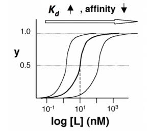
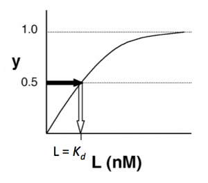
- →Then y = 0.5, and the fraction of receptors that are bound to ligand is 50%. This is why you can read $ K_d $ directly off of the plots in Nagai’s paper (compare Figure 3 and Table 1). When y = 0.5, the concentration of free calcium (our [L]) is equal to $ K_d $. This is a great rule of thumb to know.
The figures below demonstrate how to read $ K_d $ from binding curves. You will find semilog plots (right) particularly useful today, but the linear plot (left) can be a helpful visualization as well. Keep in mind that every L value is associated with a particular equilbrium value of y, while the curve as a whole gives information on the global equilibrium constant $ K_d $.

Of course, inverse pericam has multiple binding sites, and thus IPC-calcium binding is actually more complicated than the example above. The $ K_d $ reported by Nagai is called an ‘apparent $ K_d $’ because it reflects the overall avidity of multiple calcium binding sites, not their individual affinities for calcium. Normally, calmodulin has a low affinity (N-terminus) and a high affinity (C-terminus) pair of calcium binding sites. However, the E104Q mutant, which is the version of CaM used in inverse pericam, displays low affinity binding at both termini. Moreover, the Hill coefficient, which quantifies cooperativity of binding in the case of multiple sites, is reported to be 1.0 for inverse pericam. This indicates that inverse pericam behaves as if it were binding only a single calcium ion per molecule. Thus, wild-type IPC is well-described by a single apparent $ K_d $.
For any given mutant, things may be more complicated. Keep in mind that we are not directly measuring calcium binding, but instead are indirectly inferring it based on fluorescence (for both mutant and wild-type IPC). A change in fluorescence requires the participation not only of calcium, but also of M13. In addition to the four separate calcium binding sites in calmodulin, the M13 binding site influences apparent affinity and apparent cooperativity. In short, be careful about how you describe the meanings of our binding parameters in your reports.
Returning to the big picture: when you write your Protein engineering summary, be sure to consider how changes in both binding affinity and cooperativity (and even potentially raw fluorescence differences) can affect the practical utility of a sensor.
Protocols
Part 2: Prepare samples for titration curve
Tips for success
Take great care today to limit the introduction of bubbles in your samples. When expelling fluid, pipet slowly while touching the pipet tip against the bottom or side of the well.
Protocol
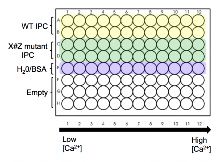
- Take a black 96-well plate, and familiarize yourself with the plate map scheme at right: top two rows are to be loaded with wild-type IPC, next two rows are to be loaded with your X#Z mutant IPC, and the final row is to be loaded with water/BSA to serve as a blank/background row.
- The dark sides of the plate reduce "cross-talk" (i.e., light leakage) between samples in adjacent wells, another potential contribution to error.
- Aliquot your wild-type protein to your plate. Use your P200 pipet to add 30 μL of protein (per well) to rows A and B of your plate.
- Aliquot you X#Z mutant IPC to your plate. Use your P200 pipet and add 30 μL of protein (per well) to rows C and D of your plate.
- Finally, add 30 μL of water with only 0.1% BSA (no IPC) to row 5(E) of your plate.
- The calcium solutions are at the front bench in shared reservoirs. Carefully carry your plate to the front bench to add these solutions with the multi-channel pipet.
- Using shared reservoir #1 (lowest calcium concentration - actually 0 nM), add 30 μL to the top five rows in the first column of the plate. Discard the pipet tips.
- Now work your way from reservoirs #2 to #12 (highest calcium concentration), and from the left-hand to the right-hand columns on your plate. Be sure to use fresh pipet tips each time! If you do contaminate a solution, let the teaching faculty know so they can put out some fresh solution. Honesty about a mistake is far preferred here to affecting every downstream experiment.
- When you are done, alert the teaching faculty and you will be taken in small groups to measure the fluorescence values for your samples.
Part 3: Fluorescence assay
- The BMC (BioMicro Center) has graciously agreed to let us use their plate reader. Walk over to building 68 with a member of the teaching staff.
- You will be shown how to set the excitation (485 nm) and emission (515 nm) wavelength on the plate reader to assay your protein.
- Your raw data will be posted on today's Discussion page and emailed to you as a .txt file so you can begin your analysis.
Reagent list
- Calcium calibration kit from Life Technologies
- Zero free calcium buffer: 10 mM EGTA in 100 mM KCl, 30 mM MOPS, pH 7.2
- 39 μM free calcium buffer: 10 mM CaEGTA in 100 mM KCl, 30 mM MOPS, pH 7.2
- Thermo Scientific Varioskan Flash Spectral Scanning Multimode Reader
Next day: Design new IPC variant


