Aligning the optical trap
Connecting the electronics
Overview
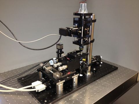
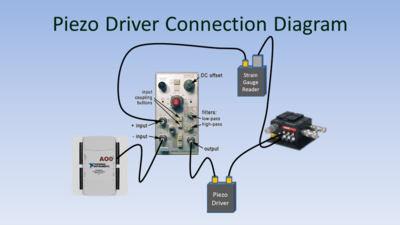
Some optical trap measurements (such as Stokes calibration, DNA tether measurement, and force clamping) require precise, computer-controlled movement of the sample. The Nanomax stage that holds the sample includes piezoelectric elements that can translate the sample over a range of approximately 20 microns in the X, Y, and Z directions. To control the position, a piezo driver applies a voltage across the piezoelectric element. The driver is part of a closed-loop system that also includes a strain gauge displacement sensor. The sensor generates a feedback signal that varies linearly with the stage position.
The piezo driver can be controlled directly by computer; however, it cannot produce the smooth, complex motions needed for some measurements. Accordingly, an alternate scheme is used to facilitate precise computer control of the stage position. The stage is controlled by a software-generated offset signal from a digital-to-analog converter connected to the computer. A differential instrumentation amplifier with unity gain is inserted in the piezo driver's control loop. The amplifier subtracts a the software-generated offset from the strain gauge reader's output. In response to a change in the offset voltage, the piezo controller adjusts the stage position until the set point is reestablished. The responsivity of the strain gauge reader is about 0.45 Volts per micron. Thus, a one volt change in the offset voltage produced by the DAC results in a movement of about 2.2 microns.
The offset scheme is implemented on the X and Y axes only.
Required materials
For this part of the procedure, you will need:
- two piezo controllers
- two strain gage readers
- a two-channel instrumentation amplifier
- a data acquisition system with at least two analog outputs and four analog inputs
- four BNC cables
- two BNC T-connectors
- four SMA to BNC cables
- six BNC to wire lead adapters.
You can use a commercial amplifier such as the Tektronix AM502 or build your own. Design files for a suitable amplifier circuit board are available on BatchPCB.com. See item number 57271.
Connections
- Connect the XDIFF output of the QPD reader to analog input AI0 on the DAQ.
- Connect DAQ output AO0 to the inverting input of the instrumentation amplifier.
- Using a BNC T-connector, connect the output monitor of the X-axis strain gage reader to the non-inverting input of the amplifier and analog input AI2 of the DAQ.
- Connect the output of the amplifier to the external input of the X-axis strain gage reader.
- In a similar manner, connect DAQ inputs AI1, AI3, output AO1, the YDIFF QPD output, Y-axis strain gage reader, and Y-axis controller to the second amplifier.
- Include an oscilloscope in the loop to monitor the signals, if you like.
If you are using a commercial amplifier, set the gain to 1, with no filtering and DC coupling, on both the inverting and non-inverting inputs.
<html>
|
<iframe src="http://techtv.mit.edu/embeds/23410?size=custom&custom_width=544&player=simple&external_stylesheet=" frameborder="0" width="544" height="338"></iframe> |
|
This video shows how to connect the optical trap electronics.
|
</html>
Aligning the optics
Fine adjusting the beam expander
<html>
|
<iframe src="http://techtv.mit.edu/embeds/19836?size=custom&custom_width=544&player=simple&external_stylesheet=" frameborder="0" width="544" height="338"></iframe> |
|
Caption
|
</html>


