Spring 2012:LFM Documentation
Contents
- 1 Light Field Microscope
Light Field Microscope
Introduction
Background and Motivation
Traditional light microscopy has been used to illuminate miniature biological specimens since the mid-1600s. Since, researchers have come to realize and (attempt to) circumvent the inherent limitations of the technique. One such limitation is that of superimposed features on the captured image. With no depth information from the subject, it is difficult to extract data specific to the focal plane from the rest of the image.
Confocal microscopy excludes light from above or below the focal plane of the image using a pinhole placed where the light from the focal plane comes to a waist. It also provides a method of visualizing 3-dimensional images and has better spatial resolution than light field microscopy, but images require scanning the entire sample at every depth of interest. Light field has the advantage of capturing relative depth information in a single photo. This additional visual information comes at a cost, however. Diffraction places an upper limit on the lateral and axial resolution of the images. We thus sacrifice spatial resolution to obtain angular resolution.
The light field microscope allows angular resolution information to be recorded in a single image. The light field is a function that represents the amount of light traveling in every direction through every point in space. By recording a sample’s light field, one can produce perspective and parallax views of the specimen. This is accomplished by inserting a microlens array in a conventional bright field microscope, and analyzing the images in silico. A microlens array is an optical component containing a spread of thousands of lenses with diameters in the micron scale. Applying 3D deconvolution to the focal stacks from the array produces a series of cross sections which allow for a 3D reconstruction of the sample.
The objective of this project is to create a light field microscope from a Lytro™ camera and the Thorlabs materials available in the 20.345 classroom, record associated documentation and code, and describe recommended experiments for use in a teaching undergraduate laboratory.
Prior Work
The only prior work we have to build upon are papers by Ren Ng's original paper on the light field microscope[1], his further work[2], his thesis[3], and some work from a postdoc at Harvard[4]. This project has not been done previously in the 20.345 lab. Ruben actually seems to have taken some shots of neurons firing, (using Calcium green - Life Technologies) and watched them in the 3d rendering.
Design Choices
In designing the setup for our project, we essentially had two choices.
- Buy the microlens array and a better CCD camera (more pixels, larger sensor)
- Buy the commercial light field camera, the Lytro™
We decided to purchase the Lytro™ for two reasons:
- Cost. The Lytro™ is selling at $399 per camera now. If we were to have purchased the components separately, the microlens array would have been >$400 on its own.
- Alignment. The Lytro™'s lens array and sensor have the pixel size, lens size, and lens pitch all perfectly suited to work in unison. In purchasing these components separately, it would have been very unlikely that we would have found products such that their sizes and alignments corresponded.
Lytro™ Camera
TheNot much is known about the lenses, just that together they exhibit a high NA and are designed to allow minimal aberration. The camera has a optical zoom controlled by the electronics on the far end of the camera. A touch screen allows the consumer to refocus the image before capturing a light field, to review all past photos still on the camera, and to refocus after capturing the image.
The camera is charged and connected to a computer through a USB cable. The application currently only works on Mac OSX. Once plugged in, the Lytro™ prompts you to install its software, then uploads the new photos it took in the last session. In this process, it transfers two types of files to the Lytro™ images folder: IMG_001.lfp and IMG_001-stk.lfp. The .lfp is the full information set, the -stk.lfp represents a stack of focal depths that the software deemed significant.
Design
Optical setup
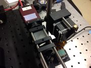
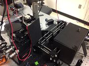
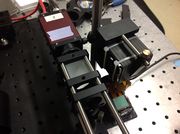
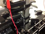
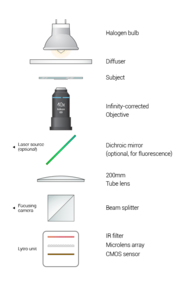
The fluorescent portion of our laser is as of yet, not built. It is very possible to add it, however, as shown in the diagram.
Evolution of the optical setup
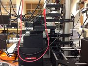
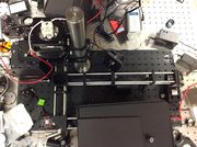
The microscope design went through a few iterations and continues to evolve. We originally tried to capture images with the Lytro™ with the provided optics. This actually ended up being more work than it was worth. Our method was basically to have the image plane lie just in front of the Lytro™ optics and then force the Lytro™ to focus on that plane using a lens tissue. This method did not always work, and in fact usually the Lytro™ would not like focusing on the light from the image instead of the surrounding lab, and switch accordingly.
We originally tried to use a 2" lens telescope to magnify the image. At first the telescope was before the tube lens, but since that contributes to aberration it was then placed after the tube lens. We tried a number of different setups to magnify the sample image such that it filled the field of view of the Lytro™ (which was fairly large considering its nice optics). We tried to put a different tube lens in the system to magnify the image with a single lens, however the led to a considerable amount of spherical aberration. We tried using a little pre-made telescope, but we found using its built in aperture that our NA was probably limited by the objective.
We noticed that once we inserted the images into LFDisplay for 3d rendering, we could see a very bright light spot that moved as we rotated our image. To counteract this, we used a medium-NA halogen bulb with a diffuser for more uniform illumination.
After much suffering, Vincent finally took the reins and tore the Lytro™ apart. He removed the front end containing the optics, and put the microlens array/sensor setup at the image plane. We took much better images this way.
Image Processing
Extracting useful information from the Lytro™ .lfp images
Getting images from Lytro™
- Pictures > Lytro™ (Show Package Contents) > images.
- You will see images organized by upload, in .lfp and -stk.lfp. The .lfp are the larger raw light field files. The -stk.lfp have already determined the most important focal depths in the image and keep only those depths.
Obtaining lfptools
- Download the lfptools from Nirav Patel on Github, or find it in Departmental > BioEng > BioEngLab > 20.309 > Students > Projects > Light Field Microscopy.
- Unzip.
- In Macs. Open Terminal. cd to folder. make.
- If you get the error "make: command not found" then download Xcode, go to Preferences>Downloads, and Install Command Line Tools.
- Move files you created to the folders HD > usr > local > bin. This folders might be invisible.
Creating .jpg image stacks from -stk.lfp
- In terminal: lfpsplitter ~/Desktop/IMG_0010-stk.lfp
- Or wherever you keep your LFP files.
- It will save in the same folder: a .json, a .txt, and .jpgs corresponding to those depths that the algorithm deemed important.
Creating .raw from .lfp
- In terminal: lfpsplitter ~/Desktop/IMG_0010.lfp
- Or wherever you keep your LFP files.
- It will save in the same folder: a .raw, a metadata .json, a private metadata .json, and a table .json.
Creating .tif from .raw
- Download raw2tiff from here
- In Macs. Open Terminal. cd to folder. make.
- If you get the error "make: command not found" then download Xcode, go to Preferences>Downloads, and Install Command Line Tools.
- Move files you created to the folders HD > usr > local > bin. This folders might be invisible.
- In terminal: raw2tiff -w 3280 -l 3280 -d short ~/Desktop/IMG_0010_imageRef0.raw ~/Desktop/Out10.tif
Dealing with the hexagonal microarray
Vincent wrote code (see below) to
Visualizing the sample in LFDisplay
- Download LFDisplay
- Run. Data > Open Input > Single Image
- If a square array (microarray was a regular grid of lenses)
- Move the center lenslet position until the red circle covers the center lenslet.
- Use dx in "Lenslet to the right" to give the program the correct distance between lenses.
- Do the same for dy in "One lenslet down."
- Move the radio button at the top to 3D to see the rendering.
List of parts
- Lytro™ camera
- 40x objective - Nikon
- Halogen bulb
- Diffuser
- CCD camera - Allied vision technologies
- Laser (optional)
- 200 mm lens
- 3 silver mirrors (2 optional)
- 1 dichroic mirror (optional)
- Beam splitter
- Stage
- Cages, legs, boxes - Thorlabs
Methodology
Disassembling the Lytro™
Be careful.
Aligning the beam path
- Beam splitter and image path - The beam splitter allows both cameras to view the image. It helps to align the CCD camera and the Lytro™ sensor to be focusing on the same place in the sample, best would be at the center of the objective to avoid illumination fall-off
- Laser
- Insert neutral density filter
- Remove telescope lenses
- Place 2 T-shirt targets on the cage
- Adjust the first two mirrors near the laser so that the laser beam is aligned straight through the center of the back of the box of the dichroic
- One t-shirt will only provide you with information on whether the laser is center at that location, but not whether it is straight.
- Replace dichroic and use lens tissue or paper to visualize beam as you adjust the angle
Making sample slides of fluorescent beads
- Weigh out 0.5g pure agarose
- Dissolve in 50 mL water (1% agarose)
- Heat and stir on hotplate or in microwave
- Water should just reach boiling
- Should turn clear
- Heat wax as well
- Make spacers out of microscope slides using the diamond tipped pen, be sure to not make too wide since the stage has a particular width
- Double sided tape: spacers onto whole microscope slide, not spaced too wide, for above reason, double-sided tape: top of spacers
- Place slide on paper towel
- Mix ~0.75 mL agarose with beads 5000:1 in an eppendorf
- Quickly pipet between spacers
- Cover exposed area with a cover slip
- Allow to cool (should be pretty quick)
- Flip, close open ends with wax, let harden
Focusing
- With optics - This process was described previously. Essentially, have the front of the camera behind the image plane, and force the Lytro to focus on the image plane using a piece of paper or something similar and using the touch screen.
- Without optics - Place microlens array/sensor in the image plane.
Results
Images
We were able to capture a few images of beads, beads in agarose, Air Force Rulings, hair, and onion cells. Our depth of focus achieved in post-processing is unfortunately low, but we believe that this can be solved with a slightly different approach to our microscope design. More results.
Issues
- Noise - We encountered a noise pattern in our resulting images that could not be categorized to the best of our (Vincent's) knowledge. The frequency domain representation of a single lenslet for our images is extremely similar to those of other lightfields which do not experience the noise, with the main difference being a differently-scaled sinc envelope caused by different lenslet size. Existing theories point to either that the lenslets have too little information and the discretization of that information causes artifacts or that there are imperfections in the microlens array. This latter theory arose after looking at the physical lens array under a microscope, and seeing that the lenses are slightly oblong.
- Light - We noticed a very bright light spot in our images that appeared to be at the depth of our actual LED light source. This light fell off in intensity very quickly. We changed our light source to a medium-NA halogen bulb with a diffuser to achieve more uniform illumination. This seems to have helped, but as you can see in our results, the illumination is still noticeably non-uniform.
- Resolution - We seem to have resolution issues (namely uneven focus) in our images. This could be a result of a few problems: 1) our sample was at an angle 2) our stage was at an angle 3) we need to really rethink our optical setup.
Code
lf_fourier_slice.m
Departmental > BioEng > BioEngLab > 20.309 > Students > Projects > Light Field Microscopy > Code
- Reads .tif from raw2tiff
- Pads image with ~5% of the image size
- Establishes lenslet stats. AKA:
- How far to the right is the closest lenslet in the same row?
- dx: 9.930846473 dy: 0
- How far diagonally is the closest lenslet one row above?
- dx: 4.965423236 dy: 8.600911765
- How far to the right is the closest lenslet in the same row?
- Gets a .png mask for the lenslet
- Calls lenslet function to make new lenslet image in a new coordinate
- Constructs a rectangular equivalent of the lightfield, turning the hex grid into a checkerboard
- Averages filled values of checkerboard onto unfilled areas. Fills in the "black spaces" with average values from white spaces.
- Results in rectangular equivalent of hex grid
lenslet.m
Departmental > BioEng > BioEngLab > 20.309 > Students > Projects > Light Field Microscopy > Code
- Takes indices, location, cell distance, half cell, and mask
- Calculates new coordinates
- Establishes new image around new coordinates
- Masks with mask.png
- Returns new image and coordinates
Other
Acknowledgments
- Steve Wasserman and Steven Nagle for their patience, humor and instruction.
- Professors Boyden and Yanik for their lectures and guidance.
- Nirav Patel, for reverse engineering the Lytro image and lfpsplitter.
- Frank Warmerdam, Andrey Kiselev, Bob Friesenhahn, Joris Van Damme and Lee Howard for raw2tiff tools.
- Other references: [5] [6] [7] [8] [9] [10] [11]
References
- ↑ [1]
- ↑ [2]
- ↑ [3]
- ↑ [4]
- ↑ G. LIPPMAN, Epreuves réversibles donnant la sensation du relief, J. Phys. 7 (4) (1908) 821–825.
- ↑ WEINSTEIN, R.S., DESCOUR, M.R., et al. 2004. An array microscope for ultrarapid virtual slide processing and telepathology. Design, fabrication, and validation study. Human Pathology 35, 11, 1303-1314.
- ↑ NG, R., LEVOY, M., BREDIF, M., DUVAL, G., HOROWITZ, M., HANRAHAN, P. 2005. Light Field Photography with a Hand-Held Plenoptic Camera. Stanford Tech Report CTSR 2005-02.
- ↑ Levoy, Marc, Ren Ng, Andrew Adams, Matthew Footer, and Mark Horowitz. "Light Field Microscopy." ACM Transactions on Graphics 25.3 (2006): 924. Print.
- ↑ Levoy, M. Zhang, Z. McDowall, I. Recording and controlling the 4D light field in a microscope. Journal of Microscopy, Volume 235, Part 2, 2009, pp. 144-162.
- ↑ Light field microscopy - Stanford 2006 (pdf)
- ↑ ZHANG, ZHENGYUN. "A Practical Introduction to Light Field Microscopy." (2010). A Practical Introduction to Light Field Microscopy. Web. 10 Mar. 2012.

