Difference between revisions of "Spring 11:QRT-PCR"
Kristin Kuhn (Talk | contribs) (→Weekly goals) |
Kristin Kuhn (Talk | contribs) (→Conclusions / Final Thoughts) |
||
| (43 intermediate revisions by one user not shown) | |||
| Line 1: | Line 1: | ||
| − | + | [[File:Pcr-setup.jpg|center|200px]] | |
| + | <big><center>QRT-PCR: 20.345 Spring 2011</center></big> | ||
| − | + | == Goal== | |
| − | + | The ultimate goal of this project is to create an inexpensive QRT-PCR kit for teaching laboratories at the undergraduate, or even high school, level. At the beginning of term, I had hoped to have a functional QRT-PCR machine by this time. Part way through term, it became clear that this would not happen, so I lowered my sights to traditional PCR alone. Unfortunately, even more setbacks occurred, and not even this early milestone was achieved. | |
| − | + | ||
| − | + | ||
| − | + | ||
| − | + | ||
| − | + | ||
| − | + | ||
| − | + | ||
| − | == | + | == Progress== |
| − | + | ||
| − | + | ||
| − | + | ||
| − | + | ||
| − | + | ||
| − | + | ||
| − | + | ||
| − | + | ||
| − | + | Some progress, however, has been made, which should be of some use to Steven, or future students. | |
| − | + | ||
| − | + | ||
| − | + | ||
| − | + | ||
| + | === Optics=== | ||
| + | At the start of term, I worked to increase the signal-to-noise ratio of the optics. After constructing and investigating several model systems of a green LED and neutral density filters, I determined that the autofluorescence of the fiber optic was producing a prohibitive amount of noise. The replacement fiber optic that was acquired also exhibited autofluorescence, so it seems that we will not be able to use a fiber optic in our design. | ||
| − | + | === Electronics=== | |
| + | A bug was discovered in the H-bridge circuit: its dynamic range is now limited to 1-5 V, instead of 0-10 V. Not even a replacement H-bridge solved the problem, so the issue is somewhere beyond the basic electrical connections. | ||
| − | + | === Labview VI=== | |
| + | Version 2.712 was updated to calculate the temperature properly from the thermistors. When thermal coupling between the block and the lid was a problem, a Tlid gain term was added to the model temperature to account for the extra power coming from the lid. When this part of the code was no longer needed, it was removed. | ||
| − | + | I also determined appropriate error constants for the PWM controller: | |
| + | * Kp = 0.09 | ||
| + | * Ki = 0.0015 | ||
| + | * Kd = 0.01 | ||
| + | Note: Ki must begin at 0. Switch to 0.0015 after the block has equilibrated to almost 95C. | ||
| + | [[File:Pcr_cycle.png|frame|none|A PCR cycle using the constants mentioned above. The green line is the temperature of the sample - notice how it stays well within typical PCR temperature ranges.]] | ||
| − | + | === Heated Lid=== | |
| + | [[File:Heated_lid.png|right|300px]] | ||
| + | A heated lid, to reduce condensation and rescue the efficacy of the PCR machine, was designed, constructed, and implemented. | ||
| − | + | The lid design (see right) consists of 29-gauge resistance wire, thermal epoxy, a copper wire, and a thermistor to measure the temperature. All of these are encased by a half-inch lens tube. 1.03 A of current through the resistance wire generates about 100C of heat, which is transferred to the tube lid via the thermal epoxy and the copper washer. | |
| − | + | ||
| − | + | ||
| − | + | ||
| − | + | ||
| − | + | ||
| − | + | ||
| − | + | ||
| − | + | ||
| − | + | 29-gauge wire was chosen to minimize the current needed to heat the wire, while still being thick enough to work with. The thermal epoxy ensures that the resistance wire does not make contact with itself, which could cause dangerously high resistance, and therefore heat, levels. | |
| − | + | ||
| − | + | ||
| − | + | ||
| − | + | ||
| − | |||
| + | == What Worked, or Not== | ||
| − | + | As could be inferred from the above, not everything I tried this semester worked as I expected. First, the fiber optic prevented progress in the optics arena, which was unforeseen and unfortunate. | |
| − | + | Then, the initial lid heater design failed. To ensure contact between the lid and its heater, pressure must be applied to the lid heater. To provide this pressure, my first design involved screwing the lid heater onto the heating block. Unfortunately, this created a great deal of thermal coupling – so much so, that to appropriately model the sample temperature, I had to introduce into the Labview VI a gain term proportional to the lid temperature. Since this was not ideal, the design was changed so that the heater balances on top of the PCR tube (which is why the metal supports in the top image are necessary). The required pressure was provided by a weight on top of the lid. This was quite effective in decoupling the lid and the sample block. | |
| − | + | ||
| − | + | A third roadblock occurred when I snapped one of the resistance wire leads coming out of the lid heater, forcing me to construct a second lid. | |
| + | In general, however, using resistance wire and thermal epoxy to heat the lid worked well - temperatures over 100C were easily achieved. | ||
| + | The Labview VI v2.712 worked well for thermal cycling, but the error constants were difficult to adjust. Please see the on-paper lab notebook for details about what constants worked when. | ||
| − | + | == Results == | |
| + | {| class="wikitable" | ||
| + | |- | ||
| + | ! Old PCR machine | ||
| + | ! Current version | ||
| + | |- | ||
| + | |[[File:First_pcr_run.png|600px]] | ||
| + | |[[File:Pcr-check-1.jpg|600px]] | ||
| + | |} | ||
| − | + | We definitely see less smearing with newer version. There is of course much work still to do. | |
| + | == Future Directions== | ||
| − | + | Important! | |
| − | ' | + | * Implement Kelly's new PWM controller, once it's ready. |
| + | * Redesign the optical setup so we don't need a fiber optic. This may involve drilling new holes in the heating block, or changing its configuration. | ||
| + | * Fine-tune the model of the sample temperature, so that we can successfully control the block temperature without needing a sample thermistor. | ||
| − | + | Less Important | |
| + | * Add a control circuit for the lid heater. | ||
| + | * Find a more elegant way to apply pressure to the lid heater. | ||
| + | * Make a another lid heater. One with a ''flat'' copper washer and a ''centered'' hole. | ||
| − | + | == Conclusions / Final Thoughts == | |
| − | + | 20.345 was a lesson in practical engineering - a long, hard, but necessary one. How do you pick up a project in the middle of its execution? How do you identify appropriate goals for your project? What about the concrete steps to reach those goals? Before this class, I was not even aware of how unprepared I was to answer these questions. I had worked on countless group projects before, but I no idea how different the challenges of an individual project could be. I wasn't checking tasks off in a lab manual with two of my peers to keep me accountable - I ''was'' the lab manual, and I was the only person keeping myself accountable. | |
| − | + | ||
| − | + | ||
| − | + | ||
| − | + | ||
| − | + | ||
| − | + | ||
| − | + | It was terrifying at first to come into lab, and have to create my own milestones and check-offs. In this way, 20.345 can be compared to a roller coaster. At the top of the roller coaster, I am quite petrified. Whose idea was this? What am I doing here? People die doing this!! But, it always ends up being pretty awesome. Yes, being in control was alarming, and I made a lot of mistakes, but it was also very rewarding, even though I didn't accomplish too much. | |
| − | + | Some of my lack of success can be attributed to mere ignorance and poor fine motor skills, but I blame most of it on not checking in with you guys often enough. I didn't go over my timeline with you; I didn't come find you when I wasn't sure what to do, or what was going on. It's a lesson I've ostensibly learned before, but I bet this time it will stick: hiding in a hole is not a good way to become less confused. Unless you're the Buddha, or something. | |
| − | + | If I were to take another individually-driven project class, I would be at a distinct advantage, because now I know what pitfalls to expect, both from the project and from myself. So much of this knowledge can only be obtained through experience, which is why I'm especially glad I took this class! | |
| − | + | ||
| − | + | On the concrete side, I learned a ton about LabView. What was before a frightening jumble of colored lines and inscrutable icons is now a language I can play around with - as long as I have the documentation close at hand! It was also very edifying to see how a circuit model of heat flow can actually be extremely useful, and what sort of constants affect that model. Because many parts of the thermal cycler are just extended versions of the DNA Melting Lab, I really felt that I was able to take my knowledge from 309 and build upon it. | |
| − | + | == Links== | |
| − | + | [[QRT-PCR | QRT-PCR project overview page]]. <br /> | |
| − | + | <!-- [[QRT-PCR:Get Started | Quickstart guide]]. <br /> --> | |
| − | + | [[Spring_11:QRT-PCR:_Progress_Notes | Detailed progress notes]]. <br /> | |
| − | + | [[Spring 11:QRT-PCR weekly reports | Weekly reports]]. <br /> | |
| − | + | [[QRT-PCR:LabView-versions | Notes on QRT-PCR Labview VI versions]]. <br /> | |
| − | + | [[QRT-PCR:Heated Lid | Research notes on the heated lid]]. <br /> | |
| − | + | ||
| − | + | ||
| − | + | ||
| − | + | ||
| − | + | ||
| − | + | ||
| − | + | ||
| − | + | ||
| − | + | ||
| − | + | ||
| − | + | ||
| − | + | ||
| − | + | ||
| − | + | ||
| − | + | ||
| − | + | ||
| − | + | ||
| − | + | ||
| − | + | ||
| − | + | ||
| − | + | ||
| − | + | ||
| − | + | ||
| − | + | ||
| − | + | ||
| − | + | ||
| − | + | ||
Latest revision as of 19:36, 19 May 2011
Contents
Goal
The ultimate goal of this project is to create an inexpensive QRT-PCR kit for teaching laboratories at the undergraduate, or even high school, level. At the beginning of term, I had hoped to have a functional QRT-PCR machine by this time. Part way through term, it became clear that this would not happen, so I lowered my sights to traditional PCR alone. Unfortunately, even more setbacks occurred, and not even this early milestone was achieved.
Progress
Some progress, however, has been made, which should be of some use to Steven, or future students.
Optics
At the start of term, I worked to increase the signal-to-noise ratio of the optics. After constructing and investigating several model systems of a green LED and neutral density filters, I determined that the autofluorescence of the fiber optic was producing a prohibitive amount of noise. The replacement fiber optic that was acquired also exhibited autofluorescence, so it seems that we will not be able to use a fiber optic in our design.
Electronics
A bug was discovered in the H-bridge circuit: its dynamic range is now limited to 1-5 V, instead of 0-10 V. Not even a replacement H-bridge solved the problem, so the issue is somewhere beyond the basic electrical connections.
Labview VI
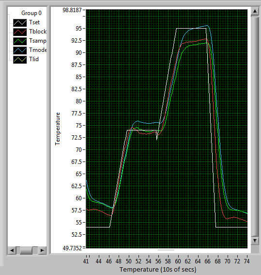
Version 2.712 was updated to calculate the temperature properly from the thermistors. When thermal coupling between the block and the lid was a problem, a Tlid gain term was added to the model temperature to account for the extra power coming from the lid. When this part of the code was no longer needed, it was removed.
I also determined appropriate error constants for the PWM controller:
- Kp = 0.09
- Ki = 0.0015
- Kd = 0.01
Note: Ki must begin at 0. Switch to 0.0015 after the block has equilibrated to almost 95C.
Heated Lid
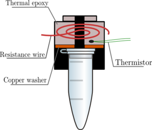
A heated lid, to reduce condensation and rescue the efficacy of the PCR machine, was designed, constructed, and implemented.
The lid design (see right) consists of 29-gauge resistance wire, thermal epoxy, a copper wire, and a thermistor to measure the temperature. All of these are encased by a half-inch lens tube. 1.03 A of current through the resistance wire generates about 100C of heat, which is transferred to the tube lid via the thermal epoxy and the copper washer.
29-gauge wire was chosen to minimize the current needed to heat the wire, while still being thick enough to work with. The thermal epoxy ensures that the resistance wire does not make contact with itself, which could cause dangerously high resistance, and therefore heat, levels.
What Worked, or Not
As could be inferred from the above, not everything I tried this semester worked as I expected. First, the fiber optic prevented progress in the optics arena, which was unforeseen and unfortunate.
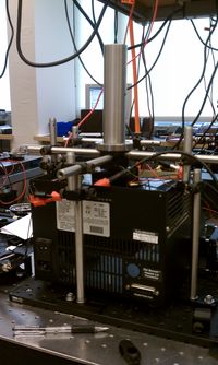
Then, the initial lid heater design failed. To ensure contact between the lid and its heater, pressure must be applied to the lid heater. To provide this pressure, my first design involved screwing the lid heater onto the heating block. Unfortunately, this created a great deal of thermal coupling – so much so, that to appropriately model the sample temperature, I had to introduce into the Labview VI a gain term proportional to the lid temperature. Since this was not ideal, the design was changed so that the heater balances on top of the PCR tube (which is why the metal supports in the top image are necessary). The required pressure was provided by a weight on top of the lid. This was quite effective in decoupling the lid and the sample block.
A third roadblock occurred when I snapped one of the resistance wire leads coming out of the lid heater, forcing me to construct a second lid.
In general, however, using resistance wire and thermal epoxy to heat the lid worked well - temperatures over 100C were easily achieved.
The Labview VI v2.712 worked well for thermal cycling, but the error constants were difficult to adjust. Please see the on-paper lab notebook for details about what constants worked when.
Results
| Old PCR machine | Current version |
|---|---|
|
|
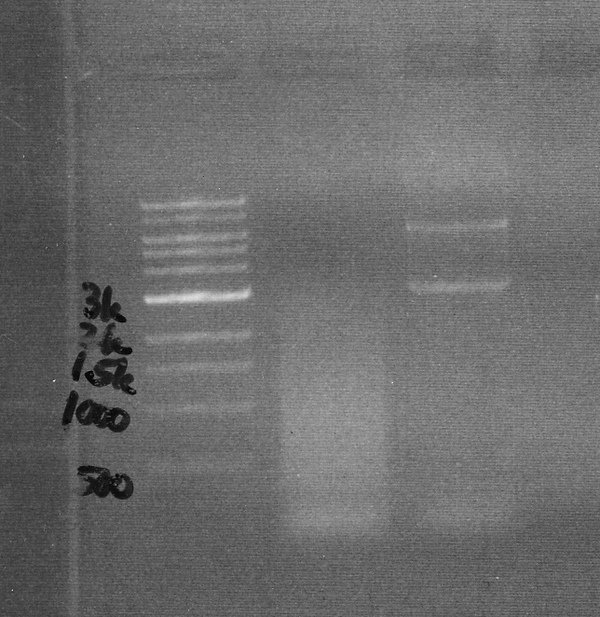
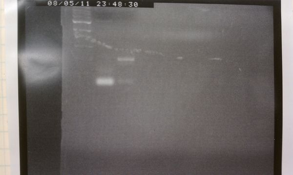
We definitely see less smearing with newer version. There is of course much work still to do.
Future Directions
Important!
- Implement Kelly's new PWM controller, once it's ready.
- Redesign the optical setup so we don't need a fiber optic. This may involve drilling new holes in the heating block, or changing its configuration.
- Fine-tune the model of the sample temperature, so that we can successfully control the block temperature without needing a sample thermistor.
Less Important
- Add a control circuit for the lid heater.
- Find a more elegant way to apply pressure to the lid heater.
- Make a another lid heater. One with a flat copper washer and a centered hole.
Conclusions / Final Thoughts
20.345 was a lesson in practical engineering - a long, hard, but necessary one. How do you pick up a project in the middle of its execution? How do you identify appropriate goals for your project? What about the concrete steps to reach those goals? Before this class, I was not even aware of how unprepared I was to answer these questions. I had worked on countless group projects before, but I no idea how different the challenges of an individual project could be. I wasn't checking tasks off in a lab manual with two of my peers to keep me accountable - I was the lab manual, and I was the only person keeping myself accountable.
It was terrifying at first to come into lab, and have to create my own milestones and check-offs. In this way, 20.345 can be compared to a roller coaster. At the top of the roller coaster, I am quite petrified. Whose idea was this? What am I doing here? People die doing this!! But, it always ends up being pretty awesome. Yes, being in control was alarming, and I made a lot of mistakes, but it was also very rewarding, even though I didn't accomplish too much.
Some of my lack of success can be attributed to mere ignorance and poor fine motor skills, but I blame most of it on not checking in with you guys often enough. I didn't go over my timeline with you; I didn't come find you when I wasn't sure what to do, or what was going on. It's a lesson I've ostensibly learned before, but I bet this time it will stick: hiding in a hole is not a good way to become less confused. Unless you're the Buddha, or something.
If I were to take another individually-driven project class, I would be at a distinct advantage, because now I know what pitfalls to expect, both from the project and from myself. So much of this knowledge can only be obtained through experience, which is why I'm especially glad I took this class!
On the concrete side, I learned a ton about LabView. What was before a frightening jumble of colored lines and inscrutable icons is now a language I can play around with - as long as I have the documentation close at hand! It was also very edifying to see how a circuit model of heat flow can actually be extremely useful, and what sort of constants affect that model. Because many parts of the thermal cycler are just extended versions of the DNA Melting Lab, I really felt that I was able to take my knowledge from 309 and build upon it.
Links
QRT-PCR project overview page.
Detailed progress notes.
Weekly reports.
Notes on QRT-PCR Labview VI versions.
Research notes on the heated lid.
