Real electronics
Real electronics sometimes behave significantly different than the idealized models presented in lecture.
Real power supplies
Limits of ideal elements: more realistic model of a battery
Recall the ideal i-v curves for our four elements, referring to Table 1 under Primary definitions .
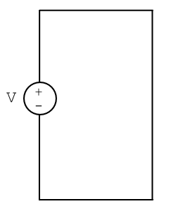
Let’s model a battery as an ideal voltage source connected to no other elements except ideal wires (Fig. 14).
What is the current flowing through this circuit? The resistance of the wires is zero, implying that the current is infinite! Therefore this model, and the associated horizontal i-v curve, is not realistic.

|

|
| Figure 14: Model for ideal battery. | Figure 15: More realistic battery model with access port. |
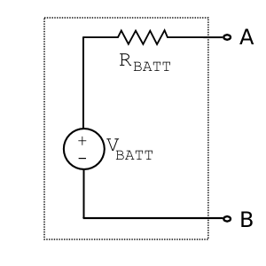
Instead, let’s model the battery as having an internal resistance, $ R_{BATT} $ (Fig. 15). To investigate the i-v curve, we’ll view the output port formed by nodes A and B.
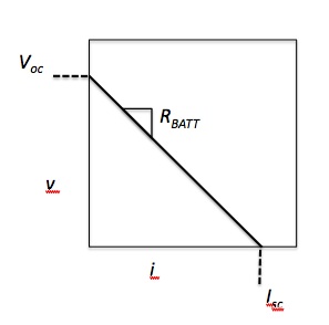
When the port is not connected to anything, resistance is infinite and current is zero. There is no load on the battery, and thus the output voltage at node A must be the full $ V_{BATT} $. This useful quantity is our by now familiar open circuit voltage, $ V_{oc} $.
Next, let’s attach a voltmeter to the port with an associated resistance $ R_m $.
When we assume that $ R_m = 0 $, $ v_A $ is shorted to ground. Thus, the current i is at its maximum, namely the short circuit current:
$ I_{sc} = \frac{V_{BATT}}{R_{BATT}} $.
These two quantities define two points on our new, more realistic, i-v curve! Presumably a line connects them, but let’s prove it by solving this simple circuit. We’ll practice our systematic approach once again.
The only unknown node voltage is $ v_A $. The other nodes are either ground or $ V_{BATT} $ by definition of a perfect conductor. Hence we want to solve KCL at $ V_{BATT} $, substituting in the relevant $ v=iR $ constitutive relations:
$ i1 + i2 = 0 = \frac{9-v_A}{R_{BATT}} + \frac{0-v_A}{R_m} = 0 $
and substituting for $ R_m $ using $ I = \frac{v_A}{R_m} $
to simplify to $ v_A = 9-I * R_{BATT} $,
indeed the equation of a line.
From the model diagram, we see that a real battery only sources a full 9V when no load is applied. As current increases, supplied voltage decreases linearly, with negative slope equalling internal resistance. Here is just one simple example of how we can learn about a system by perturbing it -- whether theoretically or experimentally. In this case we found the function relating voltage and current by imagining putting a load on the battery. Note that the equation we found is ultimately not dependent on the resistance of this added load $ R_m $.
Finally, note that the symbol for a real battery is different from that of the ideal voltage source shown earlier. A typical battery symbol looks like Figure 18A; an arbitrary number of additional lines may be shown in some cases (since most batteries actually contain multiple electrochemical cells), as in Figure 18B.

|

|
| Figure 18A: Single-cell battery symbol from public domain. | Figure 18B: Multi-cell battery symbol from public domain. |
Real voltage and current measurement devices
Real electronic breadboards
Real capacitors
Real op-amps
Amplifiers using op-amps unfortunately do not follow the golden rules to the letter. The open-loop gain is not infinite. Therefore the difference between the input voltages is not zero and the current into or out of the inputs is not zero. A realistic model of an op-amp must incorporate a specification for the input offset voltage VOS, an internal voltage that adds to whatever voltage is externally applied to the input terminals V- and V+. The model also incorporates a bias current IB for each input. These are close in real op-amps so the average is specified on the datasheet. However they are not perfectly matched and the difference is specified as the input offset current IOS. All of these non-idealities have the net effect of causing a non-zero voltage, sometimes large, at the output in a negative feedback implementation even when the input is zero. Luckily there are corrective actions available.


