Difference between revisions of "Real electronics"
Steven Nagle (Talk | contribs) |
Steven Nagle (Talk | contribs) |
||
| Line 1: | Line 1: | ||
| + | [[Category:20.309]] | ||
| + | [[Category:Electronics]] | ||
| + | {{Template:20.309}} | ||
| + | |||
Real electronics sometimes behave significantly different than the idealized models presented in lecture. | Real electronics sometimes behave significantly different than the idealized models presented in lecture. | ||
==Real op-amps== | ==Real op-amps== | ||
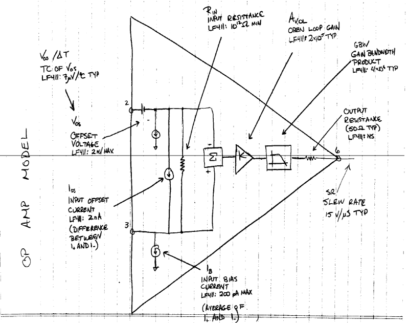
| − | [[Image:Real_Electronics_Op-amp_Model.png|frame|center| | + | [[Image:Real_Electronics_Op-amp_Model.png|frame|center|300px|A model of an op-amp highlighting its behavior in practice.]] |
Amplifiers using op-amps unfortunately do not follow the golden rules to the letter. The open-loop gain is not infinite. Therefore the difference between the input voltages is not zero and the current into or out of the inputs is not zero. A realistic model of an op-amp must incorporate a specification for the input offset voltage ''V<sub>OS</sub>'', an internal voltage that adds to whatever voltage is externally applied to the input terminals V- and V+. The model also incorporates a bias current ''I<sub>B</sub>'' for each input. These are close in real op-amps so the average is specified on the datasheet. However they are not perfectly matched and the difference is specified as the input offset current ''I<sub>OS</sub>''. All of these non-idealities have the net effect of causing a non-zero voltage, sometimes large, at the output in a negative feedback implementation even when the input is zero. Luckily there are corrective actions available. | Amplifiers using op-amps unfortunately do not follow the golden rules to the letter. The open-loop gain is not infinite. Therefore the difference between the input voltages is not zero and the current into or out of the inputs is not zero. A realistic model of an op-amp must incorporate a specification for the input offset voltage ''V<sub>OS</sub>'', an internal voltage that adds to whatever voltage is externally applied to the input terminals V- and V+. The model also incorporates a bias current ''I<sub>B</sub>'' for each input. These are close in real op-amps so the average is specified on the datasheet. However they are not perfectly matched and the difference is specified as the input offset current ''I<sub>OS</sub>''. All of these non-idealities have the net effect of causing a non-zero voltage, sometimes large, at the output in a negative feedback implementation even when the input is zero. Luckily there are corrective actions available. | ||
| + | |||
| + | {{Template:20.309 bottom}} | ||
Revision as of 03:06, 23 August 2013
Real electronics sometimes behave significantly different than the idealized models presented in lecture.
Real op-amps
Amplifiers using op-amps unfortunately do not follow the golden rules to the letter. The open-loop gain is not infinite. Therefore the difference between the input voltages is not zero and the current into or out of the inputs is not zero. A realistic model of an op-amp must incorporate a specification for the input offset voltage VOS, an internal voltage that adds to whatever voltage is externally applied to the input terminals V- and V+. The model also incorporates a bias current IB for each input. These are close in real op-amps so the average is specified on the datasheet. However they are not perfectly matched and the difference is specified as the input offset current IOS. All of these non-idealities have the net effect of causing a non-zero voltage, sometimes large, at the output in a negative feedback implementation even when the input is zero. Luckily there are corrective actions available.

