Difference between revisions of "Physical optics and resolution"
MAXINE JONAS (Talk | contribs) |
MAXINE JONAS (Talk | contribs) |
||
| Line 14: | Line 14: | ||
| − | ==Diffraction== | + | ==Diffraction and resolution== |
''Note:'' Figures in this section are from spie.org <ref>[http://spie.org/Documents/Publications/00%20STEP%20Module%2004.pdf http://spie.org/Documents/Publications/00%20STEP%20Module%2004.pdf]</ref>. | ''Note:'' Figures in this section are from spie.org <ref>[http://spie.org/Documents/Publications/00%20STEP%20Module%2004.pdf http://spie.org/Documents/Publications/00%20STEP%20Module%2004.pdf]</ref>. | ||
| Line 78: | Line 78: | ||
[[Image:20.309 130823 PinholeDiffraction.png|right|200px]] | [[Image:20.309 130823 PinholeDiffraction.png|right|200px]] | ||
[[Image:20.309 130823 SurfacePlotAiry.png|right|200px]] | [[Image:20.309 130823 SurfacePlotAiry.png|right|200px]] | ||
| + | |||
====Airy discs==== | ====Airy discs==== | ||
| Line 98: | Line 99: | ||
* It ensues that it is very difficult to achieve a resolution ''R'' less than ~ 160 nm with a light microscope (even with a big lens of small focal length ''f'' and ''sin α'' ~ 1, even with oil immersion granting ''n'' ~ 1.5, and blue visible light of &lambda ~ 400 nm)! | * It ensues that it is very difficult to achieve a resolution ''R'' less than ~ 160 nm with a light microscope (even with a big lens of small focal length ''f'' and ''sin α'' ~ 1, even with oil immersion granting ''n'' ~ 1.5, and blue visible light of &lambda ~ 400 nm)! | ||
| + | * Be aware that since real-life lenses are of finite dimensions, diffraction through a circular aperture is unavoidable and does take place in your microscope. Diffraction through a circular aperture can be simulated by convolution of the original image with a simulated Airy disk. | ||
| + | |||
| + | |||
| + | ==Enhancing image contrast== | ||
| + | |||
| + | Optical microscopy, involving visible light either transmitted through or reflected by the sample, is fettered by three categories of limitations: | ||
| + | * Diffraction limits resolution to ~ 0.2 μm (see [[Optical Microscopy Part 1c: Physical Optics and Limits of Detection#Diffraction|Diffraction]] above). | ||
| + | * Only strongly absorbing (dark) or strongly refracting objects can be successfully imaged. | ||
| + | * Background signal from points outside of the focal plane undermine image contrast. | ||
| + | |||
| + | To overcome these limitations, several specific microscopy techniques have been developed. Good overviews can be found at zeiss.com <ref>[http://zeiss-campus.magnet.fsu.edu/articles/basics/contrast.html http://zeiss-campus.magnet.fsu.edu/articles/basics/contrast.html]</ref> and fsu.edu <ref>[http://micro.magnet.fsu.edu/primer/techniques/index.html http://micro.magnet.fsu.edu/primer/techniques/index.html]</ref> (where the figures in this section were taken from) if you're interested in learning more. | ||
| + | |||
| + | {| class="wikitable" | ||
| + | |[[Image: 20.309 130823 BrightField.png|frameless|150 px]] | ||
| + | |align="left"| | ||
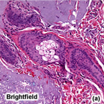
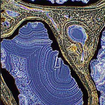
| + | * '''Bright-field microscopy''', which relies of transmitted white light illumination of the sample, can benefit from color dying of specimens, and its images' contrast can increase if the degree of absorption depends on the light wavelength and varies from point to point within the specimen. | ||
| + | |- | ||
| + | |[[Image: 20.309 130823 DarkField.png|frameless|150 px]] | ||
| + | |align="left"| | ||
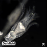
| + | * '''Dark-field microscopy''' capitalizes on oblique illumination: an opaque stop blocks direct light toward the sample, and only faint rays diffracted, reflected, and/or refracted by optical discontinuities in the sample enter the objective lens. | ||
| + | |- | ||
| + | |[[Image: 20.309 130823 PhaseContrastColor.png|frameless|150 px]] | ||
| + | |align="left"| | ||
| + | * '''Phase contrast microscopy''' takes advantage from the phase shift that arises when in-phase incident light interacts with specimen regions of varying indices of refraction. A specialized condenser containing one or several annuli, matched to phase rings in the rear plane of the objective lens amplify the phase contrast. | ||
| + | |} | ||
| + | |||
| + | also AFM | ||
| + | standing wave illumination | ||
| + | STORM | ||
| + | confocal microscopy | ||
| + | |||
| + | |||
| + | • | ||
| + | |||
| + | • | ||
| + | Polarization-dependent phase | ||
| + | contrast arises when the | ||
| + | phase shift depends on the plan | ||
| + | e of polarization of the | ||
| + | incident light. | ||
| + | • | ||
| + | Fluorescence contrast arises wh | ||
| + | en the incident light is | ||
| + | absorbed and partially reemi | ||
| + | tted at a different wavelength | ||
| + | |||
| + | |||
Revision as of 19:39, 23 August 2013
The performance of an imaging system is limited by both fundamental and technical constraints.
As we reviewed the basic principles of geometrical optics and ray tracing, treating light as a particle, we learned how aberrations (inherent to the polychromatic spectrum of light, to the nominal curvature of lenses, or introduced by human imperfection) could deform results. In this section, adding the descriptive framework of light as a wave, we'll study other factors that contribute to measurement uncertainty.
Limits of detection in microscopy can be understood as the compound of:
- aberrations
- resolution
- contrast
- detector construction
- noise.
Diffraction and resolution
Note: Figures in this section are from spie.org [1]. To ray optics, or geometrical optics, that provided intuition and equations to account for reflection and refraction and for imaging with mirrors and lenses, we can add the concepts of wave optics, also dubbed physical optics, and thereby grasp phenomena including interferences, diffraction, and polarization.
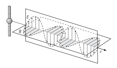
Maxwell's equations
- The set of partial differential equations unified under the term 'Maxwell's equations' describes how electric $ \vec E $ and magnetic $ \vec {B} $ fields are generated and altered by each other and by charges and currents.
- $ \nabla \cdot \vec E = {\rho \over \varepsilon_0} $
- $ \nabla \cdot \vec B = 0 $
- $ \nabla \times \vec E = - {\partial \vec B \over \partial t} $
- $ \nabla \times \vec B = \mu_0 \left ( \vec J + \varepsilon_0 {\partial \vec E \over \partial t} \right ) $
- where ρ and $ \vec J $ are the charge density and current density of a region of space, and the universal constants $ \varepsilon_0 $ and $ \mu_0 $ are the permittivity and permeability of free space. The nabla symbol $ \nabla $ denotes the three-dimensional gradient operator, $ \nabla \cdot $ the divergence operator, and $ \nabla \times $ the curl operator.
- In vacuum where there are no charges (ρ = 0) and no currents ($ \vec J = \vec 0 $), Maxwell's equations reduce to
- $ \nabla^2 \vec E = {1 \over c^2}{\partial^2 \vec E \over \partial t^2} $
- $ \nabla^2 \vec B = {1 \over c^2}{\partial^2 \vec B \over \partial t^2} $
- At large distances from the source, a spherical wave may be approximated by a plane wave, of direction of propagation $ \vec E\ \times\ \vec B $. In space and time, the electric and magnetic fields vary sinusoidally:
- $ \vec E (\vec r, t) = \vec E_0 \cos ({\vec k \cdot \vec r} - \omega t + \phi_0) $
- $ \vec B (\vec r, t) = \vec B_0 \cos ({\vec k \cdot \vec r} - \omega t + \phi_0) $
- where $ t $ is time (in seconds), $ \omega $ is the angular frequency (in radians per second), $ \vec k = (k_x,\ k_y,\ k_z) $ is the wave vector (in radians per meter), and $ \phi_0 $ is the phase angle (in radians). The wave vector is related to the angular frequency by $ k = \left\vert \vec k \right\vert = { \omega \over c } = { 2 \pi \over \lambda } $, where k is the wavenumber and λ is the wavelength.
Interferences
Key results from the theory of interactions of wave lights are:
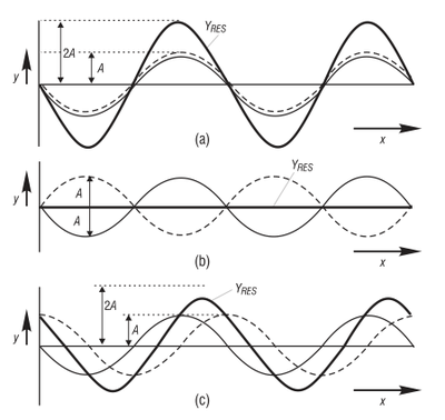
Principle of linear superposition
The (vector) electric and magnetic fields from each source of an electromagnetic wave add.
|
|
| |
|
Huygens-Fresnel principle
As a wavefront propagates, each point on the wavefront acts as a point source of secondary spherical light waves.
Fraunhofer and Fresnel diffractions
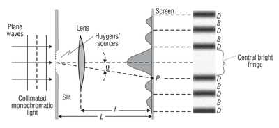
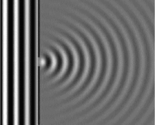
The Huygens-Fresnel principle can be used to solve diffraction of a plane wave as it passes through a slit by putting many sources along the wavefront. Fraunhofer diffraction refers to the pattern when observed far from the slit (far-field diffraction) or through a lens, while Fresnel diffraction refers to the near-field counterpart.
| Diffraction pattern through a single slit | |
|
|
Resolution
Airy discs
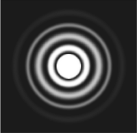
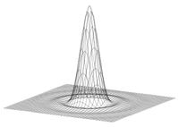
- Diffraction through a circular pinhole creates Airy discs, whose intensity on the imaging screen follows the equation
- $ I ( \theta ) = I_0 \left ( {2 J_1 {(ka \sin \theta)} \over ka \sin \theta}\right ) ^2 $
- where J1 is the Bessel function of first kind, k = 2 π / λ, and θ is the angle from the direction of light propagation.
- The half-angle beam spread to first minimum, θ, occurs at
- $ \sin \theta = 1.22 {\lambda \over D} $
- with λ the wavelength of the light and D the diameter of the round aperture (pinhole).
Rayleigh resolution
- Rayleigh criterion (a somewhat arbitrary definition of resolution!) claims that two points are resolved if the maximum of one Airy disk lies at the first zero of the other.
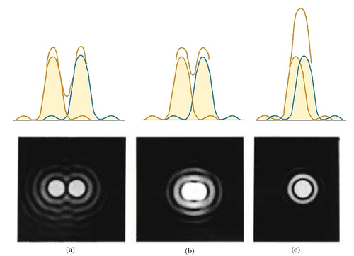
- For small angles,
- $ R \approx 1.22 {\lambda f \over D} \approx 0.61 {\lambda \over NA} $
- where $ R $ is the separation of the images of the two point objects on the film, $ f $ is the distance from the lens to the film, and NA = n sin α is the numerical aperture of the imaging lens.
- It ensues that it is very difficult to achieve a resolution R less than ~ 160 nm with a light microscope (even with a big lens of small focal length f and sin α ~ 1, even with oil immersion granting n ~ 1.5, and blue visible light of &lambda ~ 400 nm)!
- Be aware that since real-life lenses are of finite dimensions, diffraction through a circular aperture is unavoidable and does take place in your microscope. Diffraction through a circular aperture can be simulated by convolution of the original image with a simulated Airy disk.
Enhancing image contrast
Optical microscopy, involving visible light either transmitted through or reflected by the sample, is fettered by three categories of limitations:
- Diffraction limits resolution to ~ 0.2 μm (see Diffraction above).
- Only strongly absorbing (dark) or strongly refracting objects can be successfully imaged.
- Background signal from points outside of the focal plane undermine image contrast.
To overcome these limitations, several specific microscopy techniques have been developed. Good overviews can be found at zeiss.com [3] and fsu.edu [4] (where the figures in this section were taken from) if you're interested in learning more.
also AFM standing wave illumination STORM confocal microscopy
•
• Polarization-dependent phase contrast arises when the phase shift depends on the plan e of polarization of the incident light. • Fluorescence contrast arises wh en the incident light is absorbed and partially reemi tted at a different wavelength

