Difference between revisions of "Assignment 6, Part 1: build a two-color microscope"
Juliesutton (Talk | contribs) (Created page with "__NOTOC__ Congratulations! You are now half way through 20.309! While the first half of the class has focused on optics and its applications, in the upcoming weeks we will le...") |
Juliesutton (Talk | contribs) |
||
| Line 1: | Line 1: | ||
__NOTOC__ | __NOTOC__ | ||
| − | Congratulations! You are now half way through 20.309! While the first | + | Congratulations! You are now half way through 20.309! While the first part of the class has focused on optics and its applications, in the upcoming weeks we will learn about ''signals and systems''. We'll make mathematical models of ''systems'' which will allow us to determine how they can alter input ''signals'' in terms of both time and in frequency. While the framework we develop will be widely applicable (and will include systems that are electrical, mechanical and biological) we will start by building up the framework around electrical systems. One benefit of using electronics to build our framework is that in electronics we have tools like a voltmeter and an oscilloscope that allow us to measure, quantify, and visualize how signals are influenced by a system in real time. (There does not yet exist a biological equivalent to the oscilloscope.) |
| − | + | Before we can dive in to circuit building in the lab, the lectures need a bit of time to catch up and review basic circuit elements. You'll start to practice solving basic circuit problems in Part 2 of this assignment. So in the meantime, you will use your newly-formed optics skills from the first half of the semester for Part 1 of Assignment 6 to upgrade your microscope. | |
| − | Many of the following assignments will be building towards Assignment 10, where we will measure the osmotic shock response of ''S. cerevisiae''. The experiment will involve measuring how much of a protein called Hog1, is inside vs. outside of the nucleus of the yeast cell. To quantify the nuclear localization of Hog1, we will need to image two separate signals: the distribution of Hog1 in the cell, and the location of the nucleus in that cell. We'll achieve this by labeling both Hog1 and the nucleus with spectrally-separated fluorescent protein (FP) reporters. The yeast strain we will use has been engineered to fuse green fluorescent protein (GFP) to Hog1, and a fluorescent protein called tagRFP is fused to an mRNA binding protein we'll call MCP. | + | Many of the following assignments will be building towards Assignment 10, where we will measure the osmotic shock response of ''S. cerevisiae''. The experiment will involve measuring how much of a protein, called Hog1, is inside vs. outside of the nucleus of the yeast cell. To quantify the nuclear localization of Hog1, we will need to image two separate signals: the distribution of Hog1 in the cell, and the location of the nucleus in that cell. We'll achieve this by labeling both Hog1 and the nucleus with spectrally-separated fluorescent protein (FP) reporters. The yeast strain we will use has been engineered to fuse green fluorescent protein (GFP) to Hog1, and a fluorescent protein called tagRFP is fused to an mRNA binding protein we'll call MCP. |
| − | As you know from previous homework problems, imaging two colors of fluorophores will require some modifications to your microscope. Luckily, the green LED we've been using so far is a good match to excite fluorescence of tagRFP, so we need to add a blue LED to our microscope to excite GFP. (Yes, it is confusing that GREEN fluorescent protein is excited by BLUE light. RED fluorescent protein is excited by GREEN light. The naming convention of FPs refers to the color of their emission light, not their excitation light | + | As you know from previous homework problems, imaging two colors of fluorophores will require some modifications to your microscope. Luckily, the green LED we've been using so far is a good match to excite fluorescence of tagRFP, so we need to add a blue LED to our microscope to excite GFP. (Yes, it is confusing that GREEN fluorescent protein is excited by BLUE light. RED fluorescent protein is excited by GREEN light. The naming convention of FPs refers to the color of their emission light, not their excitation light!) |
Let's get started! | Let's get started! | ||
Revision as of 16:20, 22 January 2020
Congratulations! You are now half way through 20.309! While the first part of the class has focused on optics and its applications, in the upcoming weeks we will learn about signals and systems. We'll make mathematical models of systems which will allow us to determine how they can alter input signals in terms of both time and in frequency. While the framework we develop will be widely applicable (and will include systems that are electrical, mechanical and biological) we will start by building up the framework around electrical systems. One benefit of using electronics to build our framework is that in electronics we have tools like a voltmeter and an oscilloscope that allow us to measure, quantify, and visualize how signals are influenced by a system in real time. (There does not yet exist a biological equivalent to the oscilloscope.)
Before we can dive in to circuit building in the lab, the lectures need a bit of time to catch up and review basic circuit elements. You'll start to practice solving basic circuit problems in Part 2 of this assignment. So in the meantime, you will use your newly-formed optics skills from the first half of the semester for Part 1 of Assignment 6 to upgrade your microscope.
Many of the following assignments will be building towards Assignment 10, where we will measure the osmotic shock response of S. cerevisiae. The experiment will involve measuring how much of a protein, called Hog1, is inside vs. outside of the nucleus of the yeast cell. To quantify the nuclear localization of Hog1, we will need to image two separate signals: the distribution of Hog1 in the cell, and the location of the nucleus in that cell. We'll achieve this by labeling both Hog1 and the nucleus with spectrally-separated fluorescent protein (FP) reporters. The yeast strain we will use has been engineered to fuse green fluorescent protein (GFP) to Hog1, and a fluorescent protein called tagRFP is fused to an mRNA binding protein we'll call MCP.
As you know from previous homework problems, imaging two colors of fluorophores will require some modifications to your microscope. Luckily, the green LED we've been using so far is a good match to excite fluorescence of tagRFP, so we need to add a blue LED to our microscope to excite GFP. (Yes, it is confusing that GREEN fluorescent protein is excited by BLUE light. RED fluorescent protein is excited by GREEN light. The naming convention of FPs refers to the color of their emission light, not their excitation light!)
Let's get started!
New block diagram and filter sets
In Assignment 3, you chose filters to measure two colors simultaneously. Since the yeast cells will not be changing dramatically over short timescales (many seconds), we will image the two different colors sequentially. In other words, only one color LED will be on at a time. This allows us to use the same camera for both images. Since we're imaging sequentially, you could imagine mechanically flipping out the dichroic and barrier filter to be suitable for either GFP or RFP. Instead, we'll use a dual band dichroic mirror and a dual band barrier filter, which will eliminate the need for moving parts in the microscope. Actually, we've been secretly using this dual band filter all along. It should already be installed in your microscope.
The new block diagram for the microscope is shown below, along with a detailed plot of the filter spectra.


Add blue excitation LED, lenses and filter, and combining dichroic
- Gather components:
- two ER3 cage rods
- blue excitation filter (mounted in an SM1L05 lens tube)
- SM1L05 lens tubes and retaining rings
- f = 20 mm aspheric lens
- blue LED assembly
- Build your blue LED illuminator just as you did for your green one: with the excitation filter and aspheric lens as close as possible to the cage cube, and then the blue LED mount (which we will align shortly).
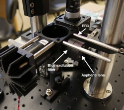 Partially assembled blue excitation path.
- Notice that one of the flanges of the blue LED heat sink has been cut to allow for clearance past the vertical post. Make sure to orient the mount accordingly.
- Mount the dichroic (DM2) to combine blue and green excitations (part T510lpxr from Chroma). Notice that this is a different dichroic than the dual band one you've already installed.
- Use the same B4C and FFM1 mount combination as you did for the dual band dichroic.
- Make sure the coated side is oriented towards the blue LED.


Align your microscope
This is a good time to make sure your microscope is functioning optimally.
- Follow the instructions in Assignment 2 to re-align the green LED excitation path.
- Once your green illumination is aligned, turn off the green LED and connect the blue LED to power. Note that you do not want to adjust any part of your microscope that will change the green alignment path, (including DM1 and M1). Use DM2 to center your blue illumination in the FOV in x and y.
- Maximize your blue illumination intensity by sliding the LED mount along the cage rods. Once you have the optimal spot, lock down the LED position using 4-40 set screws.
- Re-center the blue illumination in x and y using DM2 if necessary.
- Overview
- Part 1: feedback systems
- Part 2: fabricate a microfluidic device
- Part 3: add flow control and test your device
Back to 20.309 Main Page