Assignment 1, Part 3: Building your transillumination microscope


Overview
Yay! It's time to get your hands dirty — time to get a little mens in your manus. Step one: go to the lab. (If you are already in the lab, go on to the next step. By the way, your hands shouldn't be dirty. That's just an expression. If your hands really are dirty, then wash them with soap and water. You are going to be handling sensitive optics!)
Microscope design
There is more than one way to arrange the optics in a microscope. The particular design you will use in this lab calls for two lenses: an objective lens with focal length $ f_{objective} $ and a tube lens with focal length $ f_{tube} $. As shown in the diagram below, the sample is positioned at the front focus of the objective lens. The distance between the objective and the tube lens is equal to the sum of their focal lengths. An image with magnification $ \frac{f_{tube}}{f_{objective}} $ is formed at the back focal plane of the tube lens.

Microscope objectives generally have their magnification printed on the side, not their focal length. A simple formula converts magnification to focal length: $ f_{objective}=\frac{ETL}{M} $, where $ ETL $ is the effective tube length and $ M $ is the magnification.
There are three objective lenses available in the lab: a 10×, a 40×, and a 100×. All of these are designed to use a 200 mm tube lens to form an image on the camera. An adapter ring converts the objective mounting threads to the SM1 threads used by the lens tube system.
- Working distance (WD) is the distance between the front objective lens surface and the cover slip, and so it is also approximately the distance to the front focal plane. In order to focus an image at the back focal plane of the tube lens, i.e., on the CCD array, the sample plane must coincide with the front focal plane in a 4f microscope arrangement. The stage is added to hold the sample in this plane.
- The 100× objective is designed to be used with immersion oil. When using the 100× objective, place a drop of oil directly on the tip on the objective. Bring the drop in contact with the slide cover glass. After use, clean off the remaining oil by wicking it away with lens paper or a Kim-wipe. Do not put samples away dirty.
- Note that the back focal plane (BFP) of the objective does not necessarily coincide with the rear of the objective housing. In fact, for the Nikon 40x objective the BFP is close to the blue ring. You will find its actual location when aligning the laser path in Part 2. The 200 mm distance labeled between the back of the objective housing and the tube lens is a recommendation from Nikon to enable optimal imaging. For details on the importance and origin of this distance please ask an instructor.
Please see the Nikon Introduction to Microscope Objectives at their excellent MicroscopyU website.
The figure below shows a more detailed block diagram of the instrument you are going to build. By the time you are done, it will be capable of making wicked-cool images using two different kinds of contrast: transilluminated bright field, and epi-illuminated fluorescence. You will only use transillumination in this first part of the lab. We'll add all the stuff for epifluorescence in the next assignment. The components shown in gray are for implementing epifluorescence contrast. You can leave most of the fluorescence components out for now; you will put them in when you get to part 2. But it happens that two of the components for epifluorescence share the same optical path with transillumination — the dichroic mirror and the emission filter. If you make accommodations for these two parts while you are building this week, you won't have to take your whole microscope apart next week when you add fluorescence. Don't fret. The instructions will tell you what to do.

An example microscope made by the instructors will be available for you to examine. Look it over before you start screwing parts together to get an idea of what you are getting yourself into. The sections below introduce some of the key components the microscope is made out of. Manufacturers such as Thorlabs, Newport, and Edmund Optics sell optical components and prototyping hardware. The majority of parts in the '309 Lab come from Thorlabs, although all three of these manufacturers are represented.
Lenses
Plano-convex spherical lenses are available with focal lengths of 25, 50, 75, 100, 125, 150, 175, and 200 mm. Plano-concave lenses with focal lengths of -30 and -50 are also available. It is best to mount most optics in short (e.g. 0.5") lens tubes. It is acceptable to mount a lens between the end of a tube and a tube ring or between two tube rings. In most cases, the convex side of the lens faces toward the collimated beam; the planar side goes toward the convergent rays.
- Tip: Verify all optics before you use them by determining the focal length with a ruler. You can use the lens measuring station. Alternatively, you can use the ceiling fluorescent lamps as a light source and measure the exact distance between the lens(es) assessed and the lamp's image. Can you imagine a simple rig to evaluate negative focal lengths (of plano-concave lenses for instance)?
- Tip: As you install lenses into your microscope, put a piece of tape on the lens tube showing focal length and orientation. This will help you both during construction and put-away. Save the lens storage boxes and return components to the correct boxes when you are done.
- Handle lenses only by the edges. If a lens is dirty, first remove grit with a blast of clean air or CO2. Clean the lens by wiping with a folded piece of lens paper wetted with a drop of methanol. (Do not touch the part of the tissue you use for cleaning with your fingers.) In some cases, it may be helpful to hold the folded lens tissue in a hemostat. Ask an instructor if you need help.
General advice
You can spend a huge amount of time wandering around the lab just collecting parts, so it makes sense to grab as many parts as possible in one trip.
Most of the materials you will need for each step are shown in an image gallery, including a part number and the manufacturer's name of of the part. When you come across a part name or number that is not-all-that-self-explanatory, remember that you grew up with the freakin' Internet in your pocket. Google is your friend. If you have a question about any of the components, the manufacturer's website can be very helpful. For example, if theaprocedure calls for an SPW602 spanner wrench and you have no idea what such a thing might look like, try googling the term: "thorlabs SPW602". You will find your virtual self just a click or two away from a handsome photo and detailed specifications.
Try to be nice to the components. It should never be necessary to force anything. When in doubt, ask before you break it rather than after.
Screw sizes

Your microscope will be held together with screws. Here's how to identify the correct fastener:
Screw sizes are specified as <diameter>-<thread pitch> x <length> <type>. The diameter specification is confusing. Diameters ¼" and larger are measured in fractional inches, whereas diameters smaller than ¼" are expressed as an integer number that is defined in the Unified Thread Standard. The thread pitch is measured in threads per inch, and the length of the screw is also measured in fractional inch units. So an example screw specification is: ¼-20 x 3/4. Watch this video to see how to use a screw gauge to measure screws. (There is a white, plastic screw gauge located near the screw bins.) The type tells you what kind of head the screw has on it. We mostly use stainless steel socket head cap screws (SHCS) and set screws. If you are unfamiliar with screw types, take a look at the main screw page on the McMaster-Carr website. Notice the useful about ... links on the left side of the page. Click these links for more information about screw sizes and attributes. This link will take you to an awesome chart of SHCS sizes.
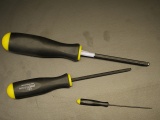
Tools
Most of the tools you will use are located in the top drawers of the cabinets under your lab station. Hex keys (also called Allen wrenches) are used to operate SHCSs. Some hex keys have a flat end and others have a ball on the end, called balldrivers. The ball makes it possible to use the driver at an angle to the screw axis, which is very useful in tight spaces. You can get things tighter (and tight things looser) with a flat driver.
Rigid optical construction
There are several ways to construct an optical systems: rails, posts, cages, tubes, and all manner of confusing, little, metallic bits. The 20.309 example microscope is constructed chiefly using the Thorlabs 30 mm cage system and 1" lens tubes. The point of these systems is to hold the optics securely in their proper positions while also allowing things require adjustment to be moved as needed. The structure of your microscope should be solid. If not, you will find the optics go out of adjustment each time you put the 'scope away. Also, in part 4 of this lab, you will use your instrument to track nanometer-scale motions of particles inside of cells. If the components of your microscope are jiggling around, you won't be able to get good results on that part of the lab.

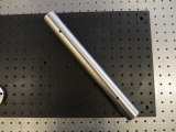
The cage system consists of stainless steel cage rods that fit into matching holes in cage plates. There are four set screws in the sides of each cage plate. (There is another similar-looking kind of cage plate with eight set screws. Make sure you use the right kind.) Tightening the set screws fixes the rods in place. The figure below shows how the set screws engage the cage rods to hold them in place. You don't need to take the set screws all of the way out — just make them loose enough so that you can insert the cage rod. When you want the cage plate to stay fixed in the same spot, use the widdy-biddy hex driver to tighten the set screw. It doesn't make sense to try and get the set screws super-tight. You'll just round off the head of the driver, instead. Make the set screws just tight enough. If you need to move the cage plate later on, just back the screw off a half turn.

The best way to mount a ordinary circular optics like lenses or mirrors or filters in a cage is to first put it in a half-inch lens tube. Then screw the tube into a cage plate. That way, you can adjust the position of the optic by sliding the cage plate. (Sliding adjustments are almost always better than rotating ones, which are usually annoying. The optical center of lenses is always a little off, and optics never lie perfectly flat. So the beam path changes when you rotate an optic. Exasperating.)
The most common kind of cage plate has threads that allow you to screw a lens tube into it. The pretty pictures in the Thorlabs catalog always show four rods. Don't fall for it — use only three rods when you build a 30mm cage. Lens tubes can't pass between two 30 mm rods; they get stranded inside the cage. "Ha ha, got you again," snickers the V.P. of Marketing whenever a hapless customer has to take their entire instrument apart in order to clean a lens or change an optic that gets stranded inside a four-rod cage. It's usually best to eliminate one of the bottom rods so you can hang stuff on the top rods. You'll see why later.
Sample stage
A precision Newport X/Y/Z stage[1] with a sample holder mounted on a post, or a Thorlabs Max312D stage, also with a sample holder, is available at each lab station. The Newport stage setup is top-heavy. Avoid accidents by ensuring that the post base is always attached to an optical breadboard or table. Leave the stage at the lab station when you are done with it. For the Thorlabs stages, it is still a good idea to bolt them down so that your area of interest (AOI) stays in your microscope field of view (FOV).
All stage axes have limited adjustment range, especially the Thorlabs stages. To deal with this, it is best to leave the stage base bolts and sample holder bolts loose and move the sample holder in x, y and z to roughly find your AOI. Once you are on or near your AOI, tighten the bolts and use the micrometers to center your image. One trick here is to get the z clamped first, then deal with x and y.
CCD camera

The microscope you will build does not have an eyepiece for direct visual observation. Instead, images will be captured with a CCD camera[2]. Its monochrome (black and white) sensor contains a grid of 656×492 square pixels that measure 7.4 μm on a side. An adapter ring converts the C-mount thread on the camera to SM1.
Light sources
There are several different lights sources available in the lab that serve different purposes. In this part of Assignment 1, we will use a light source set up for trans-illumination of the sample, i.e. the sample will be illuminated from the opposite side as the objective lens. This type of illumination only works for samples that are mostly transparent. Later on, we will use a green (532 nm) laser to excite fluorescent microscopy samples. The laser will be configured for epi-illumination - that is, it will illuminate the sample through the same objective lens that is used to image the sample. There will be more on this in Assignment 2.
For now, we will use an LED to illuminate the sample. A red or a blue LED illuminator can be used for bright-field transmitted light imaging. On one hand a blue LED yields a better bright-field resolution, however bright-field resolution is not usually critical for the samples we are interested in. On the other hand, a red LED allows simultaneous fluorescent and bright-field imaging, which you will be doing in later assignments. This can be quite useful when trying to bring a fluorescent sample into focus.
The LEDs we have in the lab produce light that is very divergent. You should use a condenser lens to collimate the light onto the sample. Since we want to collect as much of the LED light as possible, it's best to use a condenser lens with as small a focal length as possible. The smallest focal length lens we have in the lab is 25 mm.
Assemble the microscope
We recommend reproducing the general layout of the example microscope: it grants compactness and allows your device to be a stand-alone breadboard-transportable microscope. Even though you are building the bright-field imaging leg of your microscope, some of the following instructions will point you towards including key components for the fluorescence part of the microscope to save you time later.

Can you identify all the components of the block diagram? Try to think about the purpose of each additional component, and why it is laid out a particular way. Why are some sections of the light path open (strut-based structure, cage rods), while others are enclosed (Thorlabs lens tubes)?
Once you're satisfied that you understand the big picture, it's time to build your own!
Make sure to construct your microscope well. Mechanical stability will be crucial for the particle tracking experiments in the last part of the lab. The required stability specification will be achieved through good design and careful construction — not by indiscriminate over-tightening of screws.
Assemble the base
Gather the following parts:
- Tools (located in your station's drawers):
1 x 3/16 hex balldriver for 1/4-20 cap screws
1 x 9/64 hex balldriver,
1 x 0.050" hex balldriver for 4-40 set screws (tiny)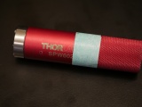
SPW602 spanner wrench


- Base components:
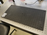
1' x 2' x 1/2" Optical breadboard (Located in the lower left cubby of the Instructor Cubbies)
1 x Vertical Thorlabs P14 mounting post (1.5" diameter, Located in the lower left cubby of the Instructor Cubbies)
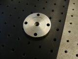
PB1 1.5" post base (Located on the west cabinet)
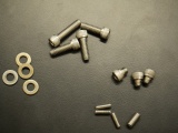
5 x 1/4-20x0.5" screws (Located on the west cabinet)


- Attach the PB1 base to the P14 post using a 1/4-20 screw.
- On a 1' x 2' x 1/2" optical breadboard, align the vertical Thorlabs P14 (1.5" diameter mounting post) with a breadboard hole that is 11 positions from a short side and 5 positions from a long side. This allows enough free space on the breadboard such that either the Newport or the Thorlabs stages may be utilized. (Note that the above picture is in error as the P14 is only 9 positions from a short side of the breadboard.)
- Secure the post base into the breadboard with 1/4-20 screws.

Assemble the illuminator
Gather parts:
- Optomechanics and LED (located in plastic bins on top of the center parts cabinet):
1 x 0.5" Lens tube (SM1L05)
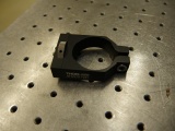
1 x 2" Cage plate (LCP01, looks like an "O" in a square)
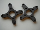
1 x Cage plate adapter (LCP02, looks like an "X")
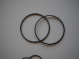
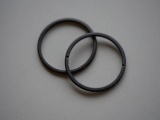
2 x 2" Retaining rings (SM2RR)
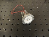
1 x red, super-bright LED (mounted in heatsink)


- Optomechanics (located on the counter above the west drawers):
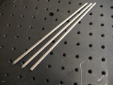
4 x ER2 cage assembly rod (The last digit of the part number is the length in inches.)
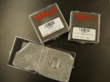
1 x 1" Retaining rings (SM1RR)


- Optics (located in the west drawers):
1 x 25mm focal length lens. This will be used as a condenser for your illuminator.

- Optomechanics (located on the west cabinet):
1 x C1500 1.5" post mounting clamp

You will also need to use an adjustable spanner wrench. The adjustable spanner resides at the lens cleaning station. There are only one or two of these in the lab. It is likely that one of your classmates neglected to return it to the proper place. This situation can frequently be remedied by yelling, "who has the adjustable spanner wrench?" at the top of your lungs. Try not to use any expletives. And please return the adjustable spanner wrench to the lens cleaning station when you are done.
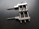
1 x SPW801 adjustable spanner wrench

- Mount the LED between two SM2RR retaining rings in an LCP01 cage plate.
- Screw in one SM2RR to a depth of 1 mm.
- Run the wires of the LED through the opening in the LCP01 and insert the LED until it is resting on the retaining ring. It will get sandwiched in-between two retaining rings.
- Add a second SM2RR retaining ring to secure the LED. Use the SPW801 adjustable spanner wrench or a small flat bladed screwdriver to tighten the retaining ring. The SPW801 can be opened until its width matches the SM2RR diameter, the separation between the ring's notches.


- Thread an SM1RR retaining ring into a SM1L05 lens tube and use the SPW602 spanner wrench to drive it about 90% of the way down the tube.
- Place the 25 mm lens in the SM1L05 lens tube with the curved side facing the external threads of the tube.
- Don't just drop the lens in. Use lens paper to gently lower the lens into the tube.
- Don't touch the lens while you are putting it in. Fingerprints are an optic's worst nightmare.
- Thread a second SM1RR retaining ring into the lens tube and tighten it with the SPW602 spanner wrench.
- Screw the lens tube into an LCP02


- Connect the LCP01 and the LCP02 together using cage rods.
- Use the tiny 4-40 set screws to secure the ER2 cage rods to the LCP01. There is no need to overnighted the screws, just make sure that they are tight enough that the rods don't slide around.
- Slide on the LCP02 containing the lens. If you're using a plano-convex lens, make sure that the curved side is oriented the way you want it to be. In this case, we want the curved side of the lens to be pointing away from the LED. (Why?) No need to tighten the LCP02 set screws quite yet - you will adjust the position of the lens in the next step.

- Connect the LED
- Turn the power supply on.
- Make sure the power supply is not enabled (green LED below the OUTPUT button is not lit).
- Use the righthand set of knobs to set the current and voltage
- Adjust the CH1/MASTER VOLTAGE knob so the display reads about 5 Volts.
- Adjust the CH1/MASTER CURRENT knob to so the display reads 0.1 Amps.
- IMPORTANT: Never set the CURRENT to a value greater than 0.5A, as this will burn out the LED.
- Pick up a red and a black cable from the cable rake in the corner of the lab. I like the ones with the flat horseshoe on one end and the alligator clip on the other.
- Connect the + (red) terminal of channel CH1 on the power supply to the red wire of the LED.
- Connect the - (black) terminal of channel CH1 on the power supply to the black wire of the LED.
| |
Double check your wiring before powering the LED. The LED can be damaged by excessive current. Limit the driving current to 0.5 A to protect the LED. |
- Press the OUTPUT button to enable the power supply and light the LED.
- Adjust the LED brightness using the power supply's CURRENT knob.


- Collimate the illuminator
- Shine the LED light at some far-away point (like on the wall). Slide the lens along the cage rods until the light comes into focus. Remember that collimated light is the same as forming an image 'at infinity'
- Tighten the set screws of the LCP02 to fix the lens-LED distance.
- Turn off the LED power supply and disconnect the alligator clips for now.

- Screw in the C1500 clamp into the LCP01 holding the LED. You will attach the illuminator to the 1.5" post on the microscope base later.
Assemble the objective cage components
Hopefully, you are becoming more comfortable finding things around the lab and assembling optomechanical components. We will stop providing quite so much detail in the assembly instructions, but don't hesitate to ask an instructor if you are confused.
- Gather the following components:
- 1 x CM1P01 Cage Cube-Mounted Turning Mirror
- 4 x ER05 0.5" Cage rods
- 4 x ER1 1" Cage rods
- 4 x ER3 3" Cage rods
- 2 x LCP01 Cage plates
- 1 x LCP02 Cage plate adapter
- 2 x C1500 1.5" post mounting clamps
- Screw in the ER05 and ER1 cage rods to the two faces of the CM1P01 cage cube
- Secure the ER3 cage rods to one of the LCP01 cage plates.


- Attach the LCP02 cage plate adaptor to the CM1P01 cube (using the smaller ER05 cage rods)
- Stack the CM1P01 cube onto the LCP01 assembly and secure the other LCP01 plate to the top end.
- Make sure that the 8-32 threaded mounting holes of the LCP01s are on the same side. Orient the turning mirror cube so that, if the 8-32 holes are closest to you, the ER1 cage rods stick out on the right side of the assembly.


- Screw in the C1500 clamps into the 8-32 threaded holes of the LCP01 cage plates.
- Slide the assembly onto the 1.5" post on the microscope's base.
- Tighten the clamps so that the distance between the top of the breadboard and the top surface of the upper LCP01 is 13.5 cm. It is important to ensure your construction is compatible with either of the two distinct stage mounting platforms available in the 20.309 lab (either Newport or Thorlabs model). If you find it inconvenient to measure this, there is a Handy Scope Height Thingama-jig floating around the lab. Ask your instructor(s). Also, note that the stages are very expensive; always lift them from the bottom.
- Mount the illuminator onto the 1.5" post above the objective assembly.


Assemble the remaining beam path
Continue assembling your microscope based on the block diagram and using the example microscope as a reference. Keep the following tips and suggestions in mind as you go:
- You want every component to be fixed to the breadboard and well-supported. (The stability of your microscope will be important later in the semester). Secure large unsupported components to the breadboard with 0.5" posts (TR2) mounted in PH2 post holders connected to BA1 bases. See the photo below. Please use a washer when securing the BA1 to the breadboard.


- Insert the C6W cage cube that will later hold the dichroic mirror required for fluorescence imaging. Be sure to keep the mounting struts fully recessed in the cube walls; their ends should not stick out, they would otherwise hinder maneuvers with dichroic-holding kinematic plate!

- Use only three cage rails to connect the C6W cage cube and the KCB containing the last silver mirror before the CCD camera, so you can easily take in and out the barrier filter (BF) that will later aid fluorescence-mode microscopy. Always place two rails at the top so that an alignment target can be hung if needed (the benefit will become more clear in the next assignment).

- Verify the focal length of the lenses you selected. If you find an optic in the wrong box: identify the optic and replace it in the correct box or label the box correctly. (Ask an instructor if you can't find the right box. There are many boxes near the wire spools behind you as you stand at the wet bench.)
- Check all your lenses for cleanliness before you use them. You'll save yourself some troubleshooting time and effort down the road!
- Make sure all your components are "leveled" (horizontal, not slanted).
- Use tube rings (and never an SM1T2, SM1V01, or SM1V05) to mount optics in lens tubes.
- Use adjustable mounting components in front of the CCD camera so you can optimize and fine-tune the camera positing with respect to the imaging lens L2. Beware: never use an SM1T2 coupler without a locking ring — they are very difficult to remove if they are tightened against a lens tube or tube ring. Also put a quick-connect in your design such that the camera CCD will end up 200 mm from the tube lens. Remember that the CCD is recessed inside the opening of the camera.

- The Nikon objective lenses are designed to be paired with a 200 mm tube lens.
- Assume that the objectives behave as ideal plano-convex lenses.
- Fine focusing will be achieved by adjusting the height of the sample stage.
- Tip: Throughout the optical microscopy lab, start the alignment with a 10× objective and then progress to 40× and 100×.
Read the instructions for microscope storage at the end of Part 4 if you will be not be completing Part 4 of Assignment 1 right away.
Back to Assignment 1
References
- Overview
- Part 1: Pre-lab questions
- Part 2: Optics bootcamp
- Part 3: Build a microscope
- Part 4: Measure stuff
Back to 20.309 Main Page