Difference between revisions of "Spring 2020 Assignment 7"
| Line 1: | Line 1: | ||
| − | + | {{Template:20.309}} | |
==Measuring action potentials== | ==Measuring action potentials== | ||
The [https://en.wikipedia.org/wiki/Patch_clamp patch clamp] is a technique for measuring voltages produced by electrically active cells such as neurons. One potential problem with the patch clamp technique is that a device must be physically attached to the neuron being measured. Connecting anything to a neuron might alter its behavior. The measurement device itself can ''distort'' the signal. This problem of ''loading'' the system to be measured affects many kinds of measurements (not just electronic ones). In this problem you will consider a simple model of the distortion in a patch clamp measurement. | The [https://en.wikipedia.org/wiki/Patch_clamp patch clamp] is a technique for measuring voltages produced by electrically active cells such as neurons. One potential problem with the patch clamp technique is that a device must be physically attached to the neuron being measured. Connecting anything to a neuron might alter its behavior. The measurement device itself can ''distort'' the signal. This problem of ''loading'' the system to be measured affects many kinds of measurements (not just electronic ones). In this problem you will consider a simple model of the distortion in a patch clamp measurement. | ||
| Line 94: | Line 94: | ||
File:Mechanical System Analogy Problem.png|Mechanical system: mass and damper | File:Mechanical System Analogy Problem.png|Mechanical system: mass and damper | ||
</gallery> | </gallery> | ||
| + | {{Template:20.309 bottom}} | ||
Revision as of 13:22, 13 April 2020

Measuring action potentials
The patch clamp is a technique for measuring voltages produced by electrically active cells such as neurons. One potential problem with the patch clamp technique is that a device must be physically attached to the neuron being measured. Connecting anything to a neuron might alter its behavior. The measurement device itself can distort the signal. This problem of loading the system to be measured affects many kinds of measurements (not just electronic ones). In this problem you will consider a simple model of the distortion in a patch clamp measurement.
A circuit model for a neuron connected to a patch clamp apparatus consists of a time-varying voltage source in series with an output impedance of 1011 Ω. There is an oscilloscope next to the neuron with an input impedance of 106 Ω and an input capacitance of 20 pFd. A new UROP in the lab attempts to measure the electrical spikes produced by a neuron (called action potentials) by connecting the patch clamp apparatus to the oscilloscope with a cable that has a capacitance of 80 pFd. Action potentials are about 100 mV in amplitude and about 1 ms in duration. You can model the noise in the oscilloscope as a random, additive, normally distributed voltage with a standard deviation of 10-3 V.

| |
|
Easy Bode plots
| |
For each of the circuits below, find the transfer function $ H(\omega)=\frac{V_{out}}{V_{in}} $. On a log-log plot, sketch the magnitude of the transfer function versus frequency. Sketch the phase angle of the transfer function versus frequency on a semi-log plot. Suggest a descriptive name for each circuit (e.g. "low-pass filter.") |
| 1 | 2 |
|---|---|

|

|
| 3 | 4 |

|

|
Harder Bode plots
| |
For each of the circuits below, find the transfer function $ H(\omega)=\frac{V_{out}}{V_{in}} $. Simplify the transfer functions using the following assumptions:
On a log-log plot, sketch the magnitude of the simplified transfer function versus frequency. Label cutoff frequencies. Sketch the phase angle of the transfer function versus frequency on a semi-log plot. Suggest a descriptive name for each circuit. Hint: both circuits have the same topology. You can save yourself a little time by solving the circuit with four generic impedances, $ Z_1 $ … $ Z_4 $, and then substituting the particular values for each circuit at the end. |
| 1 | 2 |
|---|---|

|

|
Linear systems
| |
Assuming R1 = 1 Ω and C1 = 1 F, find an equation for $ V_{out}(t) $ for each circuit given the following inputs:
Feel free to make reasonable approximations. You should only get an urge to use a calculator for the first one. |
| 1 | 2 |
|---|---|
|
|
|
Second-order system
| |
Find the transfer function $ H(\omega)=\frac{V_{out}}{I_{in}} $ for the circuit below. |

Circuit analogies
Thermal system
| |
For each of the systems below, find an analogous circuit. |
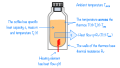
Thermal system:Coffee in a thermos
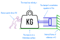
Mechanical system: mass and damper

